
Mazda CX-5 Service & Repair Manual: Mechanical
Outline
-
The sliding resistance*1 has been reduced by:
-
the adoption of a rocker arm (built into needle roller bearing)
-
reducing load on the valve spring
-
narrowing down the crankshaft journal
-
optimizing the piston skirt shape
-
adoption of a low-tension piston ring
-
lowered tensioning of the drive belt
-
A maintenance-free design for valve clearance has been achieved with the adoption of the HLA.
-
With the adoption of a piston cavity, cooling loss has been reduced.
-
The pumping loss*2 has been reduced with the adoption of the variable valve timing mechanism on both sides of the intake and exhaust.
-
The timing chain behavior has been stabilized and sliding resistance has been reduced by optimizing the shape and rigidity of the timing chain-related parts.
*2 Energy loss which occurs from each type of resistance corresponding to intake and exhaust is called pumping loss.
Structural View
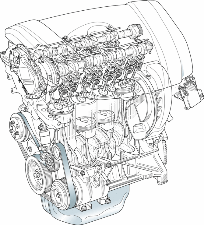
Structure
-
Consists of the following parts:
|
Cylinder head cover |
(See CYLINDER HEAD COVER [SKYACTIV-G 2.0].) |
|
|
Cylinder head |
(See CYLINDER HEAD [SKYACTIV-G 2.0].) |
|
|
Cylinder head gasket |
(See CYLINDER HEAD GASKET [SKYACTIV-G 2.0].) |
|
|
Cylinder block |
(See CYLINDER BLOCK [SKYACTIV-G 2.0].) |
|
|
Crankshaft |
(See CRANKSHAFT, MAIN BEARING [SKYACTIV-G 2.0].) |
|
|
Piston |
(See PISTON, PISTON RING, PISTON PIN [SKYACTIV-G 2.0].) |
|
|
Connecting rod |
(See CONNECTING ROD, CONNECTING ROD BEARING [SKYACTIV-G 2.0].) |
|
|
Engine front cover |
(See ENGINE FRONT COVER [SKYACTIV-G 2.0].) |
|
|
Crankshaft pulley |
(See CRANKSHAFT PULLEY [SKYACTIV-G 2.0].) |
|
|
Drive belt |
(See DRIVE BELT [SKYACTIV-G 2.0].) |
|
|
Valve mechanism (See VALVE MECHANISM [SKYACTIV-G 2.0].) |
Valve |
(See VALVE, VALVE SPRING, VALVE SEAL, VALVE GUIDE [SKYACTIV-G 2.0].) |
|
HLA |
(See HYDRAULIC LASH ADJUSTER, ROCKER ARM [SKYACTIV-G 2.0].) |
|
|
Camshaft |
(See CAMSHAFT [SKYACTIV-G 2.0].) |
|
|
Timing chain |
(See TIMING CHAIN, CHAIN TENSIONER [SKYACTIV-G 2.0].) |
|
|
Variable valve timing mechanism (See VARIABLE VALVE TIMING MECHANISM [SKYACTIV-G 2.0].) |
OCV |
(See OIL CONTROL VALVE (OCV) [SKYACTIV-G 2.0].) |
|
Hydraulic variable valve timing actuator |
(See HYDRAULIC VARIABLE VALVE TIMING ACTUATOR [SKYACTIV-G 2.0].) |
|
|
Electric variable valve timing actuator |
(See ELECTRIC VARIABLE VALVE TIMING ACTUATOR [SKYACTIV-G 2.0].) |
|
|
Electric variable valve timing relay |
(See ELECTRIC VARIABLE VALVE TIMING RELAY [SKYACTIV-G 2.0].) |
|
|
Engine mount |
(See ENGINE MOUNT [SKYACTIV-G 2.0].) |
|
 Hydraulic Variable Valve Timing Actuator
Purpose, Function
The hydraulic variable valve timing actuator operates according to the hydraulic
pressure and changes the phases of the exhaust camshaft. As a result, the open/close
per ...
 Miller Cycle Engine
Outline
The Miller cycle engine is a high-efficiency engine which achieves high fuel
economy performance by obtaining a high-expansion ratio.
The Miller cycle engine achieves a high- ...
Other materials:
Shift Position Indicator Light [Fw6 A EL, Fw6 Ax EL]
Purpose/Function
The shift position indicator light indicates the selector lever position.
Construction
The shift position indicator light is built into the instrument cluster.
Operation
The TCM sends a shift position indicator light illumination request signal ...
Warm Up Three Way Catalytic Converter (Wu Twc) Inspection
CAUTION:
Perform the following procedures, DTC P0421:00 is indicated only.
1. Connect the M-MDS to the DLC-2.
2. Start the engine and warm it up to normal operating temperature.
3. Turn off the engine.
4. Verify that the engine compression is within the specification..
If ...
Key Warning Light (Red)/Key Indicator Light (Green)
Purpose
KEY warning light (red)
The KEY warning indicator light (red) notifies the user that the engine cannot
be started, the remote transmitter is outside of the vehicle, or that there
is a malfunction in the system.
KEY indicator light (green)
The KEY indicator light (g ...
