Mazda CX-5 Service & Repair Manual: Low Clutch [Fw6 A EL, Fw6 Ax EL]
Purpose/Function
-
The low clutch operates in 1GR, 2GR, 3GR and 4GR and intermittently operates the sun gear by drive force from the turbine shaft.
-
For the low clutch, a centrifugal balance clutch has been adopted to prevent clutch drag and to assure stabilized piston thrust in all engine speed ranges.
Construction
-
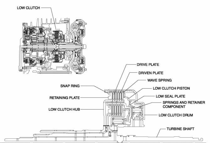
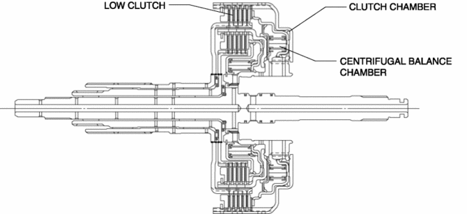
The low clutch consists of the following parts shown in the figure.
-
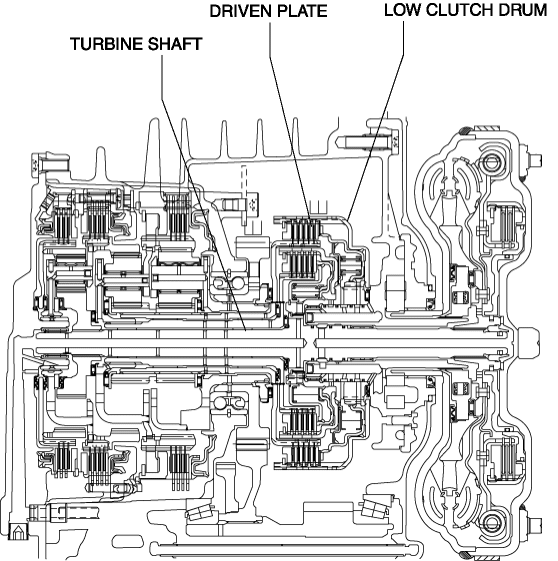
The driven plate of the low clutch is engaged with the low clutch drum. The low clutch drum is engaged with the turbine shaft and spline, and when the turbine shaft rotates, the low clutch drum and driven plate rotate as a single unit.
-
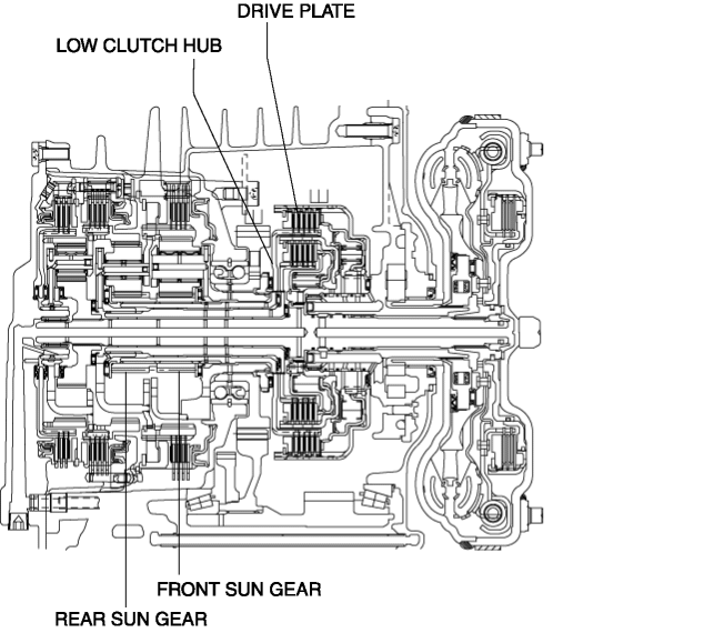
The low clutch drive plate is engaged with the low clutch hub. The low clutch hub is engaged with the front and rear sun gears, and the drive plate, low clutch hub, front sun gear and rear sun gear rotate as a single unit.
-
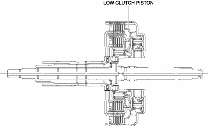
For the low clutch piston, a compact and highly reliable bonded seal piston has been adopted in which the piston and seal are molded together.
Centrifugal balance clutch
-
The centrifugal balance clutch is built into the low clutch.The centrifugal balance chamber is positioned opposing the clutch chamber for the low clutch.
-
In the centrifugal balance chamber, ATF is constantly charged through a specialized hydraulic circuit.
Operation
-
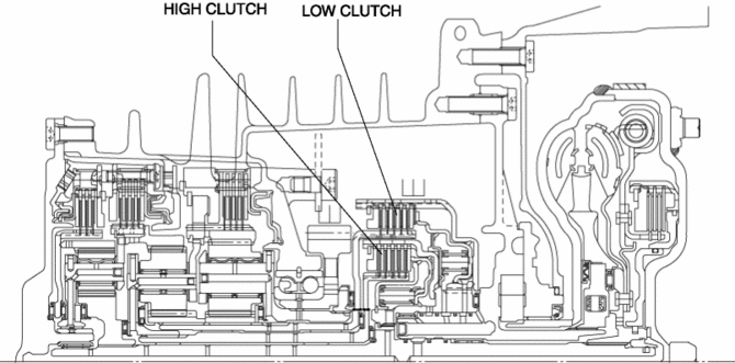
If hydraulic pressure is applied to the low clutch piston, the drive plate and driven plate are pressure bonded and drive force from the turbine shaft is transmitted to the front and rear sun gears.
-
Therefore, the following gears become the input shafts:
-
1GR by operation of the front sun gear
-
2GR by operation of the front and rear sun gears
-
3GR by operation of the front and rear sun gears and the reduction gear
-
In 4GR, the planetary gear also becomes the input shaft by the operation of the high clutch together with both the front and rear sun gears.
Centrifugal balance clutch
-
Clutch pressure not applied
-
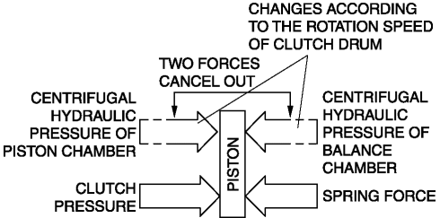
When the clutch drum rotates, centrifugal force is applied to the remaining ATF in the clutch chamber to push the piston, but centrifugal force is also applied to the ATF in the centrifugal balance chamber to force the piston to move back. As a result, the opposing forces of the clutch and balance chambers are offset and the piston does not move, preventing clutch drag.
-
Clutch pressure applied
-
When clutch pressure is applied to the clutch chamber, the piston, which overcomes the opposing centrifugal hydraulic pressure from the balance chamber and the spring force, is pushed in the direction of clutch engagement and the clutch is engaged. At this time, because the centrifugal hydraulic pressure applied to the clutch pressure in the clutch chamber is offset by the centrifugal hydraulic pressure applied to the balance chamber, the effect of piston thrust by the centrifugal force from the clutch drum rotation is eliminated. As a result, stabilized piston force in all engine speed ranges is assured, thus reducing shift shock.
 Flywheel Inspection [C66 M R]
1. Remove the flywheel..
2. Perform the following procedures to inspect the flywheel.
If there is any malfunction or it exceeds the maximum specification, replace
the flywheel..
a. ...
 Magnet Clutch [Full Auto Air Conditioner]
Purpose
The magnetic clutch transmits the rotation force from the engine to the shaft
in the A/C compressor.
Function
The magnetic clutch engages or disengages the magnetic clut ...
Other materials:
Side Air Bag Module [Standard Deployment Control System]
Purpose
When a side air bag module receives an impact from a lateral collision, the
operation (deployment) of the air bag mediates the impact to the chest, stomach,
and waist of the driver and front passenger.
Function
When a side air bag module receives an impact from a la ...
Clock Input/Output Check Mode
Activation procedure
Inspection
NOTE:
The clock input/output check mode is displayed in the following order and
returning to the previous screen is impossible.
If you want to check All LCD illuminated or Check code 1 or 2 after Check
code 6 is displayed, activate the inpu ...
Splash Shield Removal/Installation
Front
Front splash shield No.1
1. Set the mudguard aside..
2. Remove fasteners A.
3. Remove the front splash shield No.1.
4. Install in the reverse order of removal.
Front splash shield No.2
1. Remove screw B.
2. Remove fasteners C.
3. Remove the front splash shield No.2.
4. ...
