Mazda CX-5 Service & Repair Manual: Lights On Reminder Warning Alarm
Purpose
-
The lights-on reminder warning alarm notifies the driver that the TNS and headlights are not turned off.
Function
-
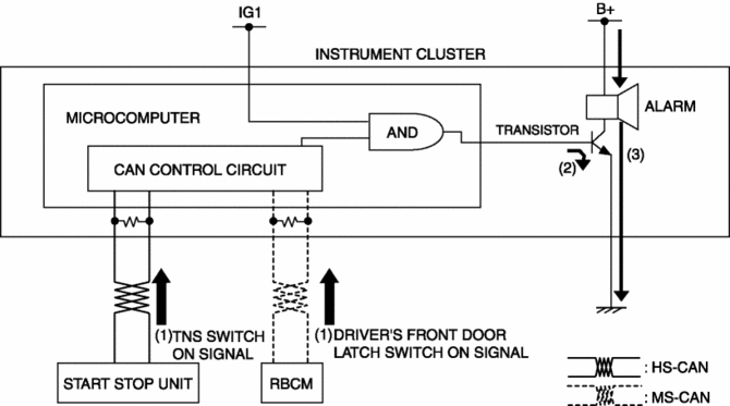
The instrument cluster receives the following vehicle condition signals via the CAN signal from the start stop unit and rear body control module (RBCM).
-
TNS switch ON signal from start stop unit (TNS and headlights illuminate)
-
Driver's front door latch switch ON signal from rear body control module (RBCM)
-
If the ignition is switched to OFF or ACC when all the above vehicle condition signals are received, the instrument cluster operates the lights-on reminder alarm.
-
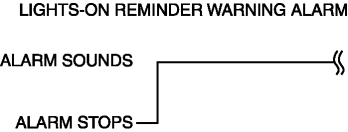
The lights-on reminder warning alarm sound pattern is as shown in the figure.
Construction
-
The lights-on reminder warning alarm sounds using the buzzer built into the instrument cluster.
Operation
1. The instrument cluster receives (1) the TNS switch ON signal from the start stop unit and driver's front door latch switch ON signal from the rear body control module (RBCM).
2. When the ignition is switched to OFF or ACC while each signal is received, the instrument cluster turns on (2) the transistor.
3. When the transistor turns on, the ground circuit of the alarm is established and the alarm sounds (3).
Fail-safe
-
Function not equipped.
 Lights On Indicator Light
Purpose
Notifies the user that the TNS or the headlights (LO) are on.
Function
Illuminates when the illumination conditions for the TNS, headlights (LO),
or parking lights are m ...
 Low Engine Coolant Temperature Indicator Light (Blue)/High Engine Coolant Temperature
Warning Light (Red)
Low Engine Coolant Temperature Indicator Light (Blue)/High Engine Coolant Temperature
Warning Light (Red)
Purpose
Low engine coolant temperature indicator light (blue)
The low engine coolant temperature indicator light (blue) notifies the driver
that the engine coolant temperature is low and va ...
Other materials:
Customer Assistance (Canada)
Satisfaction Review Process
Your complete and permanent satisfaction is of primary concern to Mazda. All
Authorized Mazda Dealers have both the knowledge and tools to keep your Mazda in
top condition. In our experience, any questions, problems, or complaints regarding
the operation of your Ma ...
Tie Rod End Replacement
1. Remove the snap pin.
2. Loosen the tie-rod end locknut.
3. Detach the tie-rod end from the steering knuckle using the SST.
4. Remove the tie-rod end locknut.
5. Place alignment marks as shown in the figure for proper installation.
6. Remove the tie-rod end.
7. Align th ...
PID/Data Monitor Inspection [Rear Body Control Module (Rbcm)]
1. Connect the M-MDS to the DLC-2.
2. After the vehicle is identified, select the following items from the initialization
screen of the M-MDS.
a. Select “DataLogger”.
b. Select “Modules”.
c. Select “R_BCM”.
3. Select the applicable PID from the PID table.
4. Verify the PID ...
