Mazda CX-5 Service & Repair Manual: Lights On Indicator Light
Purpose
-
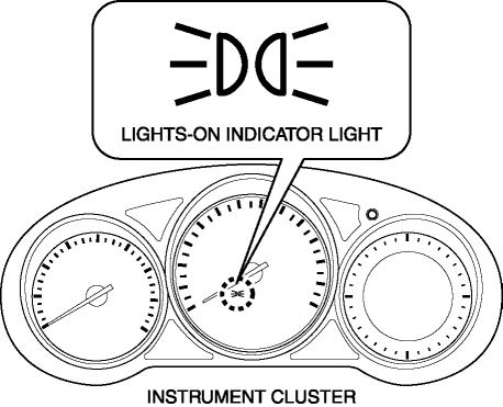
Notifies the user that the TNS or the headlights (LO) are on.
Function
-
Illuminates when the illumination conditions for the TNS, headlights (LO), or parking lights are met.
-
When the instrument cluster receives the TNS malfunction signal sent via CAN communication from the front body control module (FBCM), the indicator flashes.
Construction
-
Displayed in the instrument cluster.
Operation
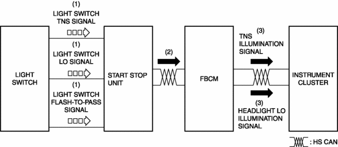
1. When the light switch is operated to the TNS, HEAD, or parking position, a light switch TNS, LO, or parking signal is sent to the start stop unit.
2. The start stop unit sends the light switch TNS, LO, or parking signal to the front body control module (FBCM).
3. The front body control module (FBCM) sends the light switch TNS, LO, or parking signal to the instrument cluster as a TNS illumination or headlight LO illumination signal.
4. When the instrument cluster receives the TNS illumination, or headlight LO illumination signal, it illuminates the lights-on indicator light.
Fail-safe
-
Function not equipped.
 Key Warning Light (Red)/Key Indicator Light (Green)
Purpose
KEY warning light (red)
The KEY warning indicator light (red) notifies the user that the engine cannot
be started, the remote transmitter is outside of the vehicle, or that there
...
 Lights On Reminder Warning Alarm
Purpose
The lights-on reminder warning alarm notifies the driver that the TNS and
headlights are not turned off.
Function
The instrument cluster receives the following vehicle c ...
Other materials:
Front Combination Light
Purpose
Parts related to the front exterior lights are grouped and housed together
such as the headlight, front turn/parking light, headlight leveling actuator,
wiring harnesses, and connectors.
Function
Each light illuminates or flashes when the light switch, turn switch, ...
Power Brake Unit Inspection
NOTE:
The following inspection methods are simple inspection methods to judge the
function of the power brake unit.
If there is any malfunction in the power brake unit, replace the power brake
unit as a single unit.
Without Using SST
Operation inspection
1. With the eng ...
How the SRS Air Bags Work
Your Mazda is equipped with the following types of SRS air bags. SRS air bags
are designed to work together with the seat belts to help to reduce injuries during
an accident.
The SRS air bags are designed to provide further protection for passengers in
addition to the seat belt functions. Be ...
