Mazda CX-5 Service & Repair Manual: Hydraulic Lash Adjuster, Rocker Arm
Purpose, Function
HLA
-
The HLA maintains the valve clearance at a constant 0 mm and maintenance-free valve clearance is realized.
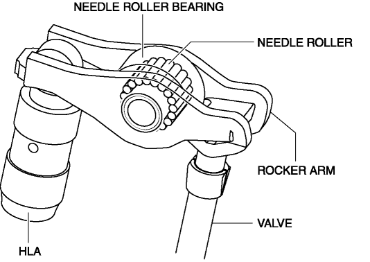
Rocker arm
-
With the adoption of the needle roller bearing built into the rocker arm, the contact to the cam employs rolling contact to reduce sliding resistance.
Construction
HLA
-
The HLA is installed to the cylinder head.
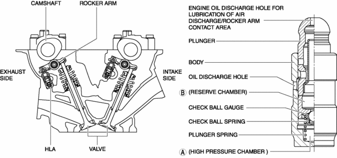
Rocker arm
-
The rocker arm is installed to the HLA and upper area of the valve.
-
The needle roller bearing is built into the rocker arm.
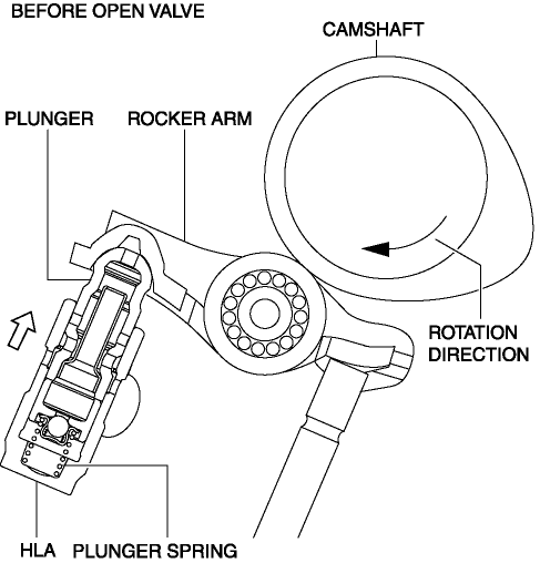
Operation
Before valve opening
1. The plunger presses up the rocker arm by the spring force of the plunger spring to maintain the valve clearance at 0 mm.
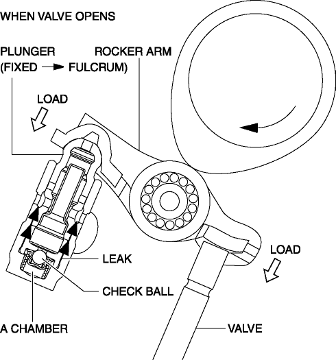
During valve opening
1. If the cam presses down the rocker arm, load is applied to the plunger and valve.
2. If load is applied to the plunger, the hydraulic pressure in the high pressure chamber (A chamber) increases and the check ball closes the hydraulic passage.
3. If the hydraulic passage is closed, the plunger is fixed becoming the rocker arm pivot point because the volume of the engine oil in the high pressure chamber is not changed.
4. The rocker arm presses down the valve.
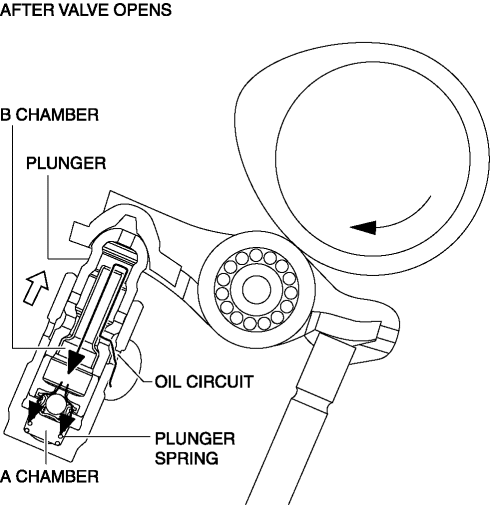
After valve opening
1. If load is not applied to the plunger, the plunger spring presses up the plunger (maintains valve clearance at 0 mm).
2. Because the capacity of the high pressure chamber (A chamber) increases in Step 1, the check ball is opened and engine oil flows from the reserve chamber (B chamber) to the high pressure chamber (A chamber) to prepare for the next step.
3. The oil in the reserve chamber (B chamber) which is decreased by supplying it to the high pressure chamber (A chamber), is supplied from the oil passage of the cylinder head.
 Hydraulic Lash Adjuster (Hla) Removal/Installation
WARNING:
A hot engine can cause severe burns. Turn off the engine and wait until it
is cool before servicing.
CAUTION:
If the camshaft is rotated with the timing chain removed ...
 Valve, Valve Spring, Valve Seal, Valve Guide
Purpose, Function
Valve
The intake valve is pressed down by the cam, the intake air passage is opened,
and air is introduced into the cylinder.
The exhaust valve is pressed down by ...
Other materials:
When Warning/Indicator Lights Illuminate/Flash
If the brake system warning light illuminates
If the light stays on after the parking brake is fully released there may be
a problem with the brakes.
Drive to the side of the road and park off the right-of-way.
You may notice that the pedal is harder to depress or that it may go closer to
t ...
Traction Control System (TCS)
The Traction Control System (TCS) enhances traction and safety by controlling
engine torque and braking.
When the TCS detects driving wheel slippage, it lowers engine torque and operates
the brakes to prevent loss of traction.
This means that on a slick surface, the engine adjusts automaticall ...
Crash Zone Sensor [Standard Deployment Control System]
Purpose
The crash zone sensor detects an impact during a frontal or frontal offset
collision to the vehicle.
Function
The crash zone sensor converts the detected impact to an electrical signal.
Construction
The crash zone sensor is built into the clutch sensor.
...
