Mazda CX-5 Service & Repair Manual: Front Door Module Panel Removal/Installation
1. Perform the front door glass preparation..
2. Disconnect the negative battery cable..
3. Remove the following parts:
a. Inner garnish.
b. Front door trim.
c. Front door speaker.
d. Front door glass.
NOTE:
-
After removing the front door trim, secure the inner handle using screws so that the procedure is performed smoothly.
4. Remove bolt A.
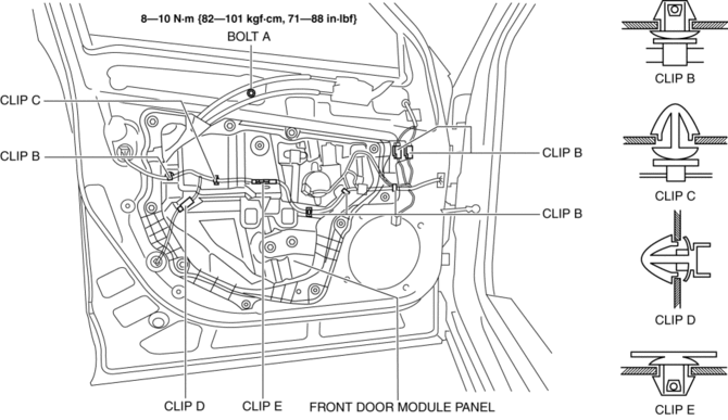
5. Detach front door wiring harness securing clips B, C, D and E.
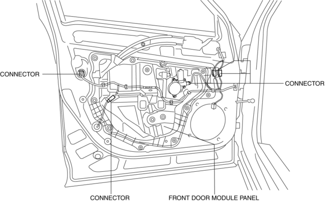
6. Disconnect the connectors shown in the figure.
7. Remove screws F.
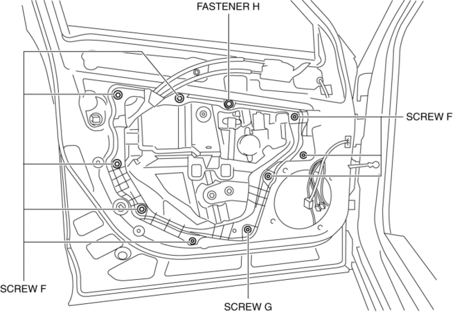
8. Remove screw G.
9. Remove fastener H.
10. Pull the front door module panel in the direction of arrow (1) shown in the figure and remove the protector and pin from the front door inner panel.
CAUTION:
-
If the protector does not come out easily from the front door inner panel, pulling the front door module panel forcibly may cause the front door module panel to deform. If the protector does not come out easily, remove the front door module panel while gradually removing the protector.
-
If the front power window regulator contacts the front door inner panel during the front door module panel removal, the coating film on the front door inner panel may get scratched, and the front door module panel and front power window regulator could be damaged. Remove the front door module panel while verifying that the front power window regulator and the front door inner panel do not contact each other.
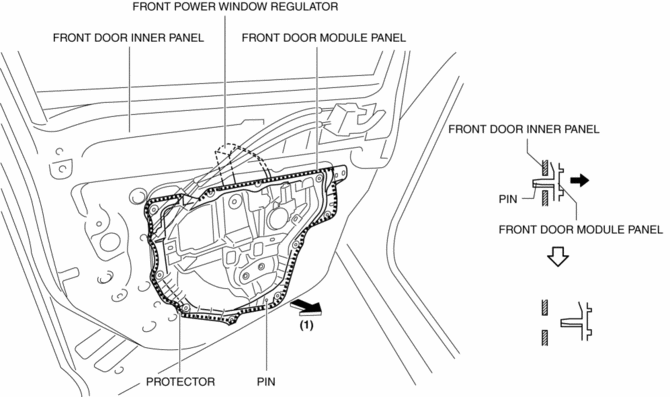
11. Move the front door module panel in the direction of arrow (2) shown in the figure so that the upper part of the front power window regulator does not contact the front door inner panel, and remove the front door module panel and the front power window regulator as a single unit.
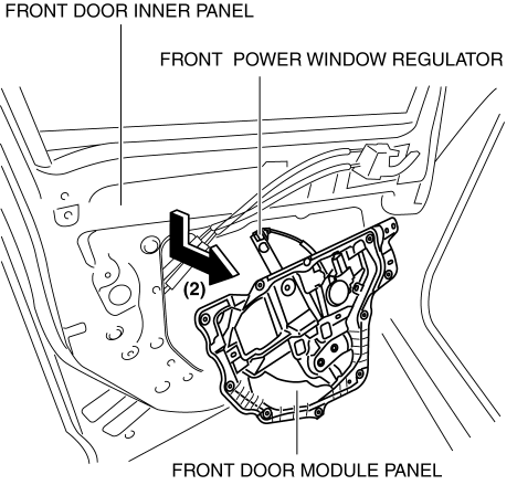
12. Remove the front power window motor..
13. Remove the front power window regulator..
14. Install in the reverse order of removal.
 Front Door Latch Switch Inspection
1. Perform the front door glass preparation..
2. Disconnect the negative battery cable..
3. Remove the following parts:
a. Inner garnish.
b. Front door trim.
c. Front door glass.
d. Front ...
 Front Door Removal/Installation
WARNING:
Removing the front door without supporting it could cause the front door
to fall and cause serious injury. Always perform the procedure with at least
one other person to prevent ...
Other materials:
Slide Motor Removal/Installation
WARNING:
Handling a side air bag improperly can accidentally operate (deploy) the
air bag, which may seriously injure you. Read the service warnings/cautions
in the Workshop Manual before handling the front seat (side air bag integrated)..
If the sliding mechanisms on both side ...
Power Brake Unit Removal/Installation
CAUTION:
Once the brake switch clearance has automatically been adjusted, it cannot
be adjusted again. Therefore, replace the switch with a new one when replacing
the power brake unit or performing any procedure that changes the pedal stroke.
1. Remove the battery and battery tra ...
Auto Leveling Sensor Inspection
1. Disconnect the negative battery cable..
2. Remove the auto leveling sensor..
3. Prepare three dry cell batteries (1.5 V).
4. Connect the three dry cell batteries in a series.
5. Connect the positive pole of the dry cell battery to auto leveling sensor
terminal C, and the negative po ...
