Mazda CX-5 Service & Repair Manual: Cylinder Head
Outline
-
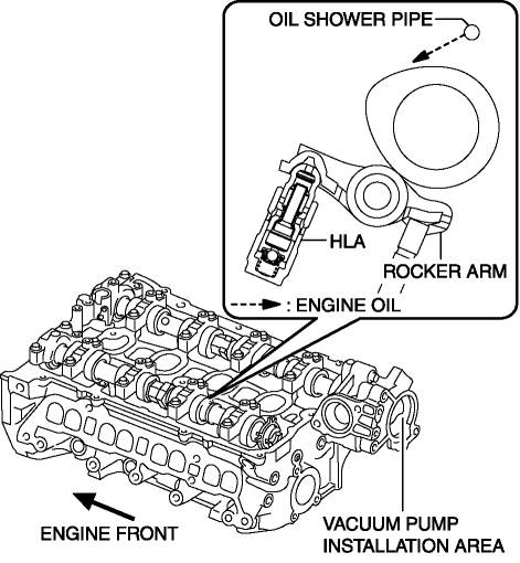
With the adoption of the rocker arm (built into needle roller bearing), the sliding resistance has been reduced.
-
With the adoption of the HLA, the valve clearance is maintained at 0 mm at all the times.
-
The contact point of the rocker arm and cam is lubricated by the engine oil injected from the oil shower pipe.
-
Because the SKYACTIV-G 2.0 is implemented on the Miller cycle, the intake manifold vacuum is insufficient during the intake valve opening timing. To improve this, the intake manifold vacuum insufficiency is supplemented with the adoption of the vacuum pump..

Purpose, Function
-
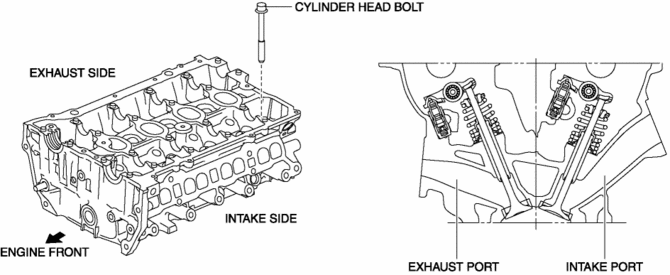
The cylinder head forms the combustion chamber and intake and exhaust ports.
Construction
-
The lightweight cylinder head is made of aluminum alloy with excellent thermal conductivity.
-
Designing a compact pentroof combustion chamber and positioning the spark plugs on the top of the combustion chamber has improved the combustion efficiency.
-
There are two intake valves and two exhaust valves per cylinder for a total of four valves and the intake/exhaust type has been changed to a cross-flow type, improving intake and exhaust efficiency.
-
High pressurization is achieved by optimizing the intake port shape, improving the tumble ratio, increasing the combustion speed, and suppressing knocking.
-
With the adoption of plastic region tightening* for the cylinder head bolts, axial force has been stabilized.

 Cylinder Head Gasket
Purpose, Function
The cylinder head gasket is installed between the cylinder head and cylinder
block to prevent leakage of air-fuel mixture, combustion gas, engine oil, and
engine coolant ...
 Hydraulic Lash Adjuster (Hla) Inspection
HLA Troubleshooting
Item
Occurrence
Possible cause
Action
1
After replacing oil, sound occurs when starting engine
...
Other materials:
Bsm Indicator Light Flashes While Not Under Bsm Indicator Light Flashing Conditions
(No Combination Switch Operation (Turn Signal Switch)) [Blind Spot Monitoring (Bsm)]
Description
BSM indicator light flashes while not under BSM indicator light-flashing
conditions (no combination switch operation (turn signal switch)
The BSM indicator light flashes despite not satisfying the BSM indicator
light flashing ...
Hazard Warning Flasher
The hazard warning lights should always be used when you stop on or near a roadway
in an emergency.
The hazard warning lights warn other drivers that your vehicle is a traffic hazard
and that they must take extreme caution when near it.
Depress the hazard warning flasher and all the turn sig ...
Crankshaft Position (CKP) Sensor Removal/Installation
CAUTION:
When foreign material such as an iron chip is on the CKP sensor, it can cause
abnormal output from the sensor because of flux turbulence and adversely affect
the engine control. Be sure there is no foreign material on the CKP sensor when
replacing.
Do not assemble t ...
