
Mazda CX-5 Service & Repair Manual: Auxiliary Jack/Usb Port Inspection
Auxiliary jack inspection
1. Disconnect the negative battery cable..
2. Remove the following parts:
a. Upper console.
b. Auxiliary jack/USB port.
3. Connect a commercially-available plug to the external input unit.
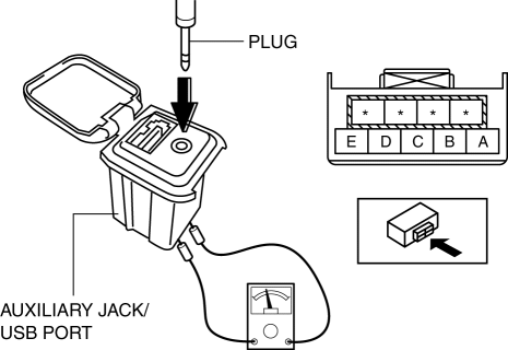
4. Verify that the continuity between the external input unit terminals is as indicated in the table.
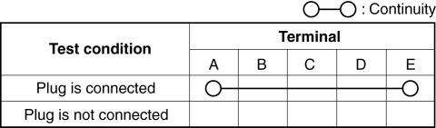
-
If not as indicated in the table, replace the external input unit.
USB port inspection
1. Disconnect the negative battery cable..
2. Remove the following parts:
a. Upper console.
b. Auxiliary jack/USB port.
3. Insert the pins to positions UA', UB', UC', and UD' shown in the figure from the side of the USB device insertion area for the external input unit, and verify the continuity at the insertion side and terminal side of the USB device.
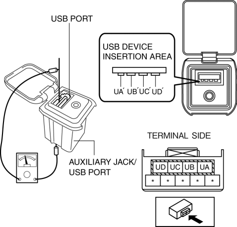
4. Verify that the continuity at the insertion side and terminal side of the USB device is as indicated in the table.
NOTE:
-
When inspecting the USB device insertion side, touch it with a paper clip or similar thin pin without directly inserting a tester into the terminals.
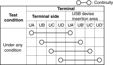
-
If not as indicated in the table, replace the external input unit.
 Auxiliary Jack/Usb Port
NOTE:
“iPod” is a registered trademark of Apple Inc. in the United States and other
countries.
Purpose, Function
The Auxiliary jack/USB port outputs the audio signals of co ...
 Auxiliary Jack/Usb Port Removal/Installation
1. Disconnect the negative battery cable..
2. Remove the upper console..
3. While pressing the auxiliary jack/USB port. tabs in the direction of the arrows
(1) shown in the figure, press the aux ...
Other materials:
Afs (Adaptive Front Lighting System)
Outline
The AFS is a system which enhances the range of visibility when the headlights
are turned on by pointing the optical axis of the headlights in the direction
in which the vehicle is advancing according to the steering operation.
Function
The AFS is controlled by the ...
Manual Transaxle Oil Inspection [C66 M R]
1. Park the vehicle on level ground.
2. Remove the front under cover No.2..
3. Remove the oil level plug and gasket.
4. Verify that the manual transaxle oil is near the brim of the plug port.
When the manual transaxle oil level is lower than the lower limit, add manual
transaxl ...
Rear Seat Back Striker Removal/Installation
1. Disconnect the negative battery cable..
2. Press the push knob to fold the rear seat back.
3. Remove the following parts:
a. Trunk board.
b. Trunk end trim.
c. Rear scuff plate.
d. Trunk side trim.
4. Remove the bolts.
5. Remove the rear seat back striker.
6. Install in the ...
