Mazda CX-5 Service & Repair Manual: Curtain Air Bag Module Removal/Installation [Standard Deployment Control System]
WARNING:
-
Handling the air bag module improperly can accidentally deploy the air bag module, which may seriously injure you. Read the air bag system service warnings and cautions before handling the air bag module..
1. Switch the ignition to off.
2. Disconnect the negative battery cable and wait for 1 min or more
..
3. Partially peel back the seaming welts.
4. Remove the following parts:
a. Sunroof seaming welt (with sunroof).
b. A-pillar trim.
c. Front map light.
d. Sunvisor.
e. Front scuff plate.
f. Rear scuff plate.
g. B-pillar lower trim.
h. Front seat belt adjuster cover.
i. Upper anchor of the front seat belt.
j. B-pillar upper trim.
k. Assist handle.
l. Trunk board.
m. Trunk end trim.
n. Trunk side trim.
o. D-pillar trim.
p. C-pillar trim.
5. Remove the headliner..
6. Using a flathead screwdriver, lift the locking device carefully, however do not remove it.
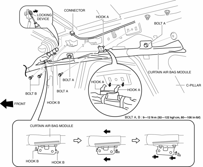
7. Disconnect the connector.
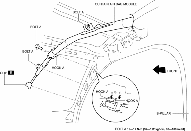
8. Remove the clip..
9. Remove bolts A.
10. Remove bolts B.
11. Pull hook A in the direction shown in the figure and remove it from the body.
12. Pull hook B in the direction shown in the figure and remove it from the body.
13. Remove the curtain air bag module.
14. Install in the reverse order of removal.
15. Switch the ignition ON (engine off or on).
16. Verify that the air bag system warning light illuminates for approx. 6 s
and goes out.
-
If the air bag system warning light does not operate normally, refer to the on-board diagnostic system (air bag system) and perform inspection of the system..
Clip Removal Note
1. Pull out the pin with flathead screwdriver as shown in the figure.
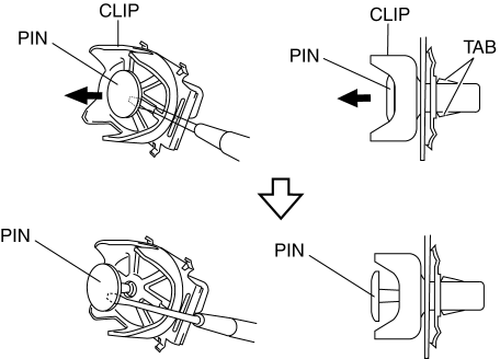
2. Insert a flathead screwdriver into shown in the figure.
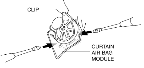
3. While pulling the curtain air bag in the direction of the arrow shown in the figure (1), detach tabs by prying with a flathead screwdriver in the direction of the arrow (2) (3).
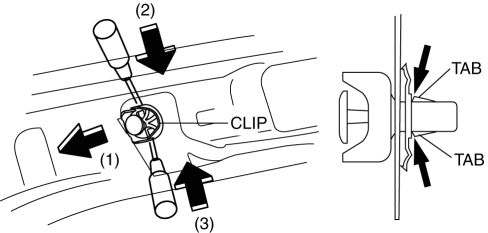
4. Remove the clip from the body.
 Crash Zone Sensor [Standard Deployment Control System]
Purpose
The crash zone sensor detects an impact during a frontal or frontal offset
collision to the vehicle.
Function
The crash zone sensor converts the detected impact to an el ...
 Curtain Air Bag Module [Standard Deployment Control System]
Purpose
When a curtain air bag module receives an impact from a lateral collision,
the operation (deployment) of the air bag mediates the impact to the head of
the driver and front passen ...
Other materials:
Master Cylinder
Purpose/Function
With the adoption of the master cylinder having an enlarged diameter (20.64
mm {0.8126 in}), brake pedal operability has been improved.
For vehicles with DSC, the diameter of the pipe between the master cylinder
and the DSC HU/CM has been increased, improving re ...
Body Panel
Outline
The multi-load path and triple H-shaped structure of distributing the power
absorbed at the collision were used for the body shell.
A ring structure has been adopted for the triple H structure, realizing top-level
crash safety performance.
Crushable structure fro ...
Filament Repair
1. Clean the filament using isopropyl alcohol.
2. Attach tape to both sides of the filament.
3. Using a small brush or marking pen, apply silver paint.
4. After 2—3 min, carefully remove the tape without damaging the applied
area.
CAUTION:
Do not operate the rear window defro ...
