Mazda CX-5 Service & Repair Manual: Brake Fluid Air Bleeding
CAUTION:
-
Brake fluid will damage painted surfaces. Be careful not to spill any on painted surfaces. If it is spilled, wipe it off immediately.
NOTE:
-
Keep the fluid level in the brake fluid reserve tank at 3/4 full or more during the air bleeding.
-
Begin air bleeding with the brake caliper that is furthest from the master cylinder.
-
Brake fluid type
-
SAE J1703 or FMVSS116 DOT-3
1. Remove the cap from the brake fluid reserved tank and add brake fluid.
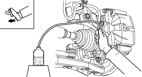
2. Remove the bleeder cap on the brake caliper, and attach a vinyl tube to the bleeder screw.
3. Place the other end of the vinyl tube in a clear container and fill the container with fluid during air bleeding.
4. Working with two people, one should pump the brake pedal several times and depress and hold the pedal down.
5. While the brake pedal is depressed, the other should loosen the bleeder screw using a commercially available flare nut wrench, drain out any fluid containing air bubbles, and tighten the bleeder screw.
-
Tightening torque
-
6.9—9.8 N·m {71—99 kgf·cm, 62—86 in·lbf}
6. Repeat Steps 4 and 5 until no air bubbles are seen.
7. Perform air bleeding as described in the above procedures for all brake calipers.
8. Clean the brake calipers.
9. After air bleeding, inspect the following:
-
Brake operation
-
Fluid leakage
-
Fluid level
 2 6 Brake [Fw6 A EL, Fw6 Ax EL]
Purpose/Function
The 2-6 brake locks the rear internal gear and reduction planetary carrier
while in 2GR and 6GR.
Construction
The 2-6 brake consists of the following parts show ...
 Brake Fluid Inspection
1. Verify that the brake fluid level in the brake fluid reserve tank is between
the MAX and MIN marks.
If the brake fluid level is below the MIN mark, add brake fluid.
...
Other materials:
Steering Gear And Linkage Removal/Installation
CAUTION:
Performing the following procedures without first removing the ABS wheel-speed
sensor may possibly cause an open circuit in the wiring harness if it is pulled
by mistake. Before performing the following procedures, disconnect the ABS wheel-speed
sensor (axle side) and fix t ...
Antenna Feeder No.3 Removal/Installation
1. Disconnect the negative battery cable..
2. Remove the following parts:
a. B-pillar lower trim.
b. Front seat belt adjusting cover.
c. Front seat belt upper anchor installation bolt.
d. B-pillar upper trim.
e. Trunk board.
f. Trunk end trim.
g. Trunk side trim.
h. D-pillar trim. ...
Magnet Clutch [Full Auto Air Conditioner]
Purpose
The magnetic clutch transmits the rotation force from the engine to the shaft
in the A/C compressor.
Function
The magnetic clutch engages or disengages the magnetic clutch and the A/C
turns on or off by switching the power transmission from the engine.
C ...
