
Mazda CX-5 Service & Repair Manual: Auxiliary Jack/Usb Port
NOTE:
-
“iPod” is a registered trademark of Apple Inc. in the United States and other countries.
Purpose, Function
-
The Auxiliary jack/USB port outputs the audio signals of commercially-available portable audio, a USB device, or an iPod connected to the Auxiliary jack/USB port to the audio unit.
Construction
-
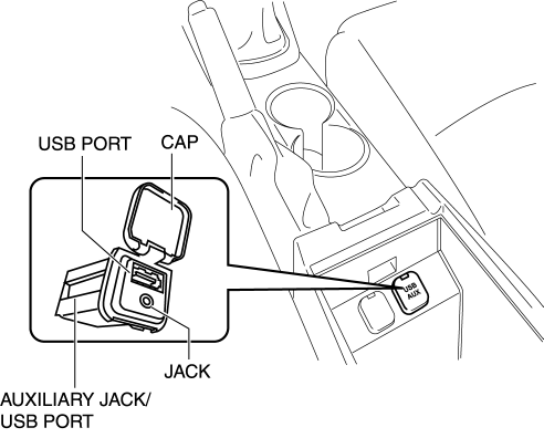
Auxiliary jack/USB port is installed inside the rear console.
-
An auxiliary jack and USB port are equipped.
Operation
Auxiliary jack
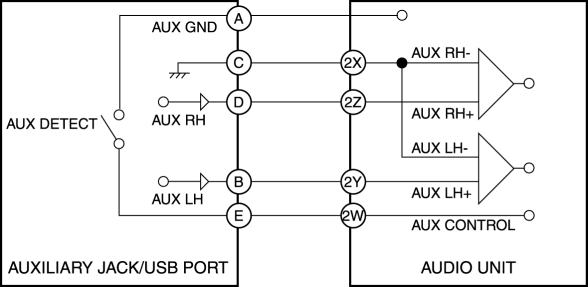
1. When the plug of a portable audio unit is connected to the Auxiliary jack/USB port, the Auxiliary jack/USB port sends the audio signal from the portable audio device to the audio unit.
2. When the audio unit is switched to AUX mode using the AUX switch for the audio panel switch (without color LCD)/display (with color LCD) or the commander switch, the audio unit outputs the audio signal sent from the auxiliary jack/USB port to the speakers.
USB port
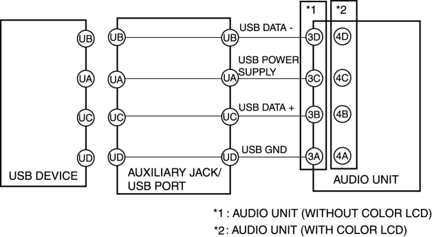
1. When the USB device/iPod is connected to the USB port for the auxiliary jack/USB port, the auxiliary jack/USB port sends the audio signal of the USB device/iPod to the audio unit.
2. When the audio unit is switched to the USB mode using the USB switch of the audio panel switch (without color LCD)/display (without color LCD) or the commander switch, the audio unit outputs the audio signal sent from the auxiliary jack/USB port to the speakers.
 Audio Unit Removal/Installation
Removal
1. Disconnect the negative battery cable.
2. Remove the decoration panel..
3. Remove the bolt.
4. Remove the screws.
NOTE:
When removing the audio unit, the audio unit cou ...
 Auxiliary Jack/Usb Port Inspection
Auxiliary jack inspection
1. Disconnect the negative battery cable..
2. Remove the following parts:
a. Upper console.
b. Auxiliary jack/USB port.
3. Connect a commercially-available plug to t ...
Other materials:
Front Wheel Hub Bolt Replacement
1. Remove the brake calliper component from the steering knuckle and suspend
it out of the way using a cable.
2. Remove the disc plate.
3. Remove the wheel hub bolt using the SST as shown in the figure.
4. Place a new wheel hub bolt in the wheel hub.
5. Install the wheel hub by placi ...
Lumber Support Motor Inspection
WARNING:
Handling a side air bag improperly can accidentally operate (deploy) the
air bag, which may seriously injure you. Read the service warnings/cautions
in the Workshop Manual before handling the front seat (side air bag integrated)..
1. Disconnect the negative battery cable ...
Starter Disassembly/Assembly [Skyactiv G 2.0]
1. Disassemble in the order indicated in the table.
2. Assemble in the reverse order of disassembly.
1
Magnetic switch
2
Adjustment washer
3
Rear housing
4
Brush and brush holder
...
