
Mazda CX-5 Service & Repair Manual: Liftgate Removal/Installation
WARNING:
-
Removing the stay damper, liftgate hinge securing bolt, or liftgate without supporting the liftgate may cause the liftgate to fall off and injure you. When removing the stay damper, liftgate hinge, or liftgate, always use two persons to perform the work.
1. Disconnect the negative battery cable..
2. Remove the liftgate upper trim..
3. Disconnect the connectors shown in the figure.
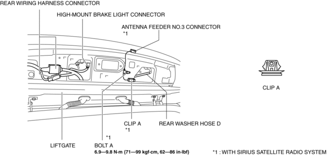
4. Disconnect rear washer hose D.
5. Remove bolt A. (with SIRIUS satellite radio system)
6. Remove clip A. (with SIRIUS satellite radio system)
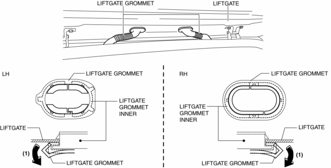
7. Partially peel the liftgate grommet in the direction of arrow (1) shown in the figure, and remove the liftgate grommet from the liftgate grommet inner.
8. Using a tape-wrapped flathead screwdriver, press the liftgate grommet inner tabs B in the directions of arrows (2) and (3) shown in the figure and remove the liftgate grommet inner from the liftgate in the direction of arrow (4).
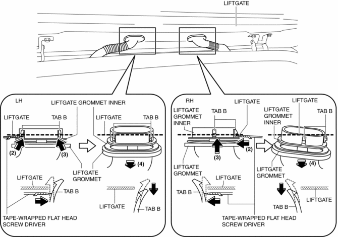
9. Remove rear washer hose D and the wiring harness from the liftgate and set them aside.
10. Using a tape-wrapped flathead screwdriver, remove the stay damper securing band in the direction of arrows (5) shown in the figure.
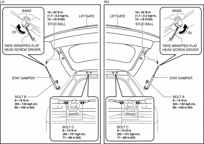
11. Remove bolt B.
12. Remove the stay damper.
13. Remove the stud ball.
14. Remove bolts C.
15. Remove the liftgate.
16. Install in the reverse order of removal.
17. Adjust the liftgate..
 Liftgate Recess Removal/Installation
1. Insert a tape-wrapped flathead screwdriver in the position indicated by the
arrow in the figure and detach hooks A.
2. Remove the liftgate recess in the direction of the arrow shown in the ...
 Liftgate Side Trim Removal/Installation
1. Remove the liftgate upper trim..
2. Remove the fastener A.
3. Take the shaded area shown in the figure, and pull the liftgate side trim
in the direction of the arrow (1) while detaching clips ...
Other materials:
Extractor Chamber Removal/Installation
1. Disconnect the negative battery cable..
2. Remove the following parts:
a. Rear splash shield.
b. Rear combination light.
c. Rear bumper.
3. Insert a tape-wrapped flathead screwdriver shown in the figure and remove
clips in the direction of arrow (1).
4. Remove the extractor cham ...
Power Window Subswitch Inspection
1. Disconnect the negative battery cable..
2. Remove the power window subswitch..
3. Verify that the continuity between the power window subswitch terminals is
as indicated in the table.
If not as indicated in the table, replace the power window subswitch.
...
Clock Input/Output Check Mode
Activation procedure
Inspection
NOTE:
The clock input/output check mode is displayed in the following order and
returning to the previous screen is impossible.
If you want to check All LCD illuminated or Check code 1 or 2 after Check
code 6 is displayed, activate the inpu ...
