Mazda CX-5 Service & Repair Manual: Accelerator Pedal Position (App) Sensor Inspection
Voltage Inspection
NOTE:
-
Because the APP sensor is integrated in the accelerator pedal, replacing the APP sensor includes replacement of the accelerator pedal.
1. Connect the M-MDS to the DLC?2.
2. Switch the ignition ON (engine off or on).
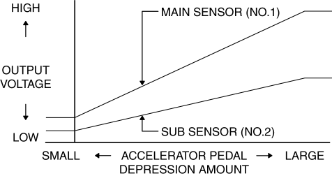
3. Verify that the APP sensor output voltage (PID: APP1, APP2) increases according to the increase in the accelerator opening angle when the accelerator opening angle is gradually increased..
-
If verified, go to the next step.
-
If not as verified, replace the accelerator pedal..
4. Verify that the APP sensor output voltage (PID: APP1, APP2) is within the specification when the accelerator pedal is depressed and not depressed..
-
If not as specified, replace the accelerator pedal..
Specification
 Throttle Position (TP) Sensor
Purpose/Function
Detects the throttle valve opening/closing condition, which operates in accordance
with the accelerator pedal operation, as basic information for mainly determining
the f ...
 Accelerator Pedal Position (App) Sensor
Purpose/Function
Detects the accelerator pedal depression amount as basic information for
mainly determining the throttle valve opening.
Detects the accelerator pedal depression amou ...
Other materials:
Cowl Upper Plate Removal [Panel Replacement]
Symbol Mark
Removal Procedure
1. Drill the 9 locations indicated by (A) shown in the figure.
2. Drill the 2 locations by (B) from the front wheel housing side shown in the
figure.
3. Drill the 2 locations indicated by (C) from the inside shown in the figure.
4. Remove the cowl upp ...
Rear Door Trim Removal/Installation
1. Insert a tape-wrapped flathead screwdriver in the position indicated by the
arrow (1) in the figure and remove the inner handle cover while detach tabs A, pin
B.
2. Remove the screw C.
3. Remove the cover D, then remove the screw E.
4. Take the shaded area shown in the figur ...
Inspection Of SST (Deployment Tool) [Two Step Deployment Control System]
1. Before using the SST (49 H066 002), inspect its operation.
Inspection Procedure
1. Follow the steps below to inspect the SST (49 H066 002).
If not as indicated in the table, replace the SST (49 H066 002) because
it has a malfunction.
WARNING:
Do not use a malfu ...
