Mazda CX-5 Service & Repair Manual: A/C Unit Removal/Installation
1. Disconnect the negative battery cable..
2. Discharge the refrigerant..
3. Drain the engine coolant..
CAUTION:
-
If moisture or foreign material enters the refrigeration cycle, cooling ability will be lowered and abnormal noise or other malfunction could occur. Always plug open fittings immediately after removing any refrigeration cycle parts.
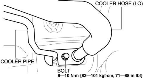
4. Remove the bolt, then disconnect the cooler hose (LO) and cooler pipe.
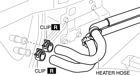
5. Disconnect the heater hose.
6. Remove the following parts:
a. Windshield wiper arm and blade.
b. Cowl grille.
c. Windshield wiper motor.
d. Front scuff plate.
e. Front side trim.
f. Glove compartment.
g. Dashboard under cover.
h. Decoration panel.
i. Center panel.
j. Audio unit (with audio unit).
k. Front console box.
l. Shift lever knob (MTX).
m. Shift panel.
n. Upper panel.
o. Rear console.
p. Side wall.
q. Front console.
r. Shift lever component (MTX).
s. Selector lever component (ATX).
t. Hood release lever from the lower panel.
u. Lower panel.
v. Knee bolster.
w. Climate control unit.
x. Column cover.
y. Driver-side air bag module.
z. Steering wheel.
aa. Steering shaft.
ab. Switch panel.
ac. Meter hood.
ad. Instrument cluster.
ae. A-pillar trim.
7. Remove the dashboard..
8. Remove the blower unit..
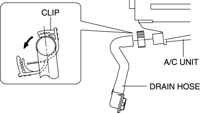
9. Disconnect the drain hose.
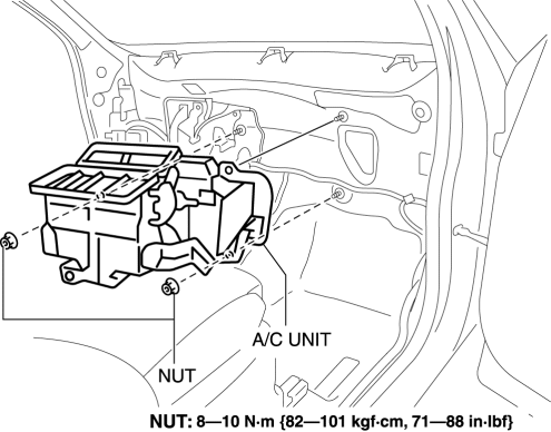
10. Remove the nut, then remove the A/C unit. Do not allow compressor oil to spill.
11. Install in the reverse order of removal..
12. Inspect for engine coolant leakage..
13. Perform the refrigerant system performance test..
A/C Unit Installation Note
1. When replacing the A/C unit or evaporator, add compressor oil to the refrigerant cycle.
-
Supplemental oil amount (approx. quantity)
-
40 ml {40 cc, 1.4 fl oz}
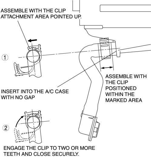
Drain Hose Installation Note
1. Install the clip as shown in the figure.
 A/C Unit Disassembly/Assembly
1. Disassemble in the order indicated in the table.
CAUTION:
If a non-specified grease is used, it may result in abnormal noise or improper
operation of the links. Apply only the specifie ...
 Air Intake Actuator Inspection [Full Auto Air Conditioner]
1. Connect battery positive voltage to air intake actuator terminal B (or C),
connect terminal C (or B) to ground, and then verify that the air intake actuator
operates as shown in the table.
...
Other materials:
Center-Rear Position Seat Belt
Before using the center-rear lap/shoulder belt make sure tongue (A) and anchor
buckle (B) are fastened.
Fastening the Seat Belt
1. Grasp the seat belt tongue (C).
2. Slowly pull out the lap/shoulder belt.
3. Insert the seat belt tongue (C) into the seat belt buckle (D) until you hear
a cli ...
Column Cover Removal/Installation
1. Pull down the steering wheel.
2. Press the shaded area shown in the figure using your thumb, and lift the upper
column cover in the direction of arrow (1).
3. Pull the upper column cover in the direction of the arrow (2) and remove it
while detaching pins A, tabs B and guides C.
4. ...
Hazard Warning Switch Inspection
1. Disconnect the negative battery cable..
2. Remove the decoration panel..
3. Verify that the continuity between the hazard warning switch terminals is
as indicated in the table.
If the continuity is as indicated in the table, go to the next step.
If not as indicated i ...
