Mazda CX-5 Service & Repair Manual: Wheel Hub Component Removal/Installation [2 Wd]
CAUTION:
-
Performing the following procedures without first removing the ABS wheel-speed sensor may possibly cause an open circuit in the wiring harness if it is pulled by mistake. Before performing the following procedures, disconnect the ABS wheel-speed sensor connector (body side) and fix the wiring harness to an appropriate place where it will not be pulled by mistake while servicing the vehicle.
1. When working on the left side of the vehicle, disconnect the auto leveling sensor link. .
2. Remove in the order indicated in the table.
3. Install in the reverse order of removal.
4. Inspect the rear wheel alignment..
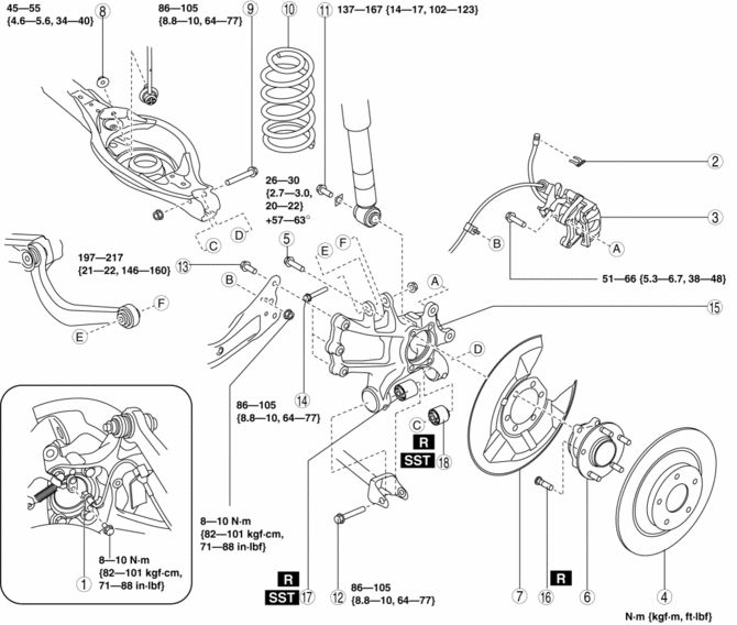
|
1 |
ABS wheel-speed sensor |
|
2 |
Brake hose clip |
|
3 |
Brake caliper component . |
|
4 |
Disc plate |
|
5 |
Bolt (wheel hub) (See Bolt (Wheel Hub) Installation Note.) |
|
6 |
Wheel hub |
|
7 |
Dust cover |
|
8 |
Rear stabilizer control link lower side nut |
|
9 |
Rear lower arm outer bolt . |
|
10 |
Rear coil spring (See REAR COIL SPRING REMOVAL/INSTALLATION.) |
|
11 |
Rear shock absorber lower bolt (See REAR SHOCK ABSORBER REMOVAL/INSTALLATION.) |
|
12 |
Rear lateral link outer bolt (See REAR LATERAL LINK REMOVAL/INSTALLATION.) |
|
13 |
Rear trailing link installation bolt (See REAR LATERAL LINK REMOVAL/INSTALLATION.) |
|
14 |
Bolt (rear upper arm outer side) |
|
15 |
Hub support |
|
16 |
Wheel hub bolt . |
|
17 |
Hub support bushing (front) . |
|
18 |
Hub support bushing (rear) . |
Brake Caliper Component Removal Note
1. Remove the brake caliper component from the trailing link and suspend it out of the way using a cable.
Rear Lower Arm Outer Bolt Removal Note
1. Support the rear lower arm using a jack.
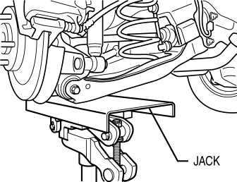
2. Remove the rear lower arm outer bolt.
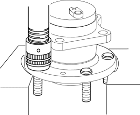
Wheel Hub Bolt Removal Note
NOTE:
-
The wheel hub bolts do not need to be removed unless they are being replaced.
1. Remove the wheel hub bolt using a press.
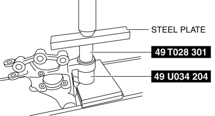
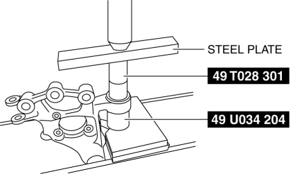
Hub Support Bushing (Front) Removal Note
1. Mark the hub Support as shown in the figure.
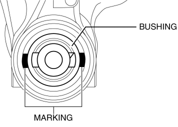
2. Press the rear hub support bushing (front) out using the SSTs
.
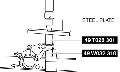
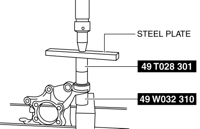
Hub Support Bushing (Rear) Removal Note
1. Mark the hub Support as shown in the figure.
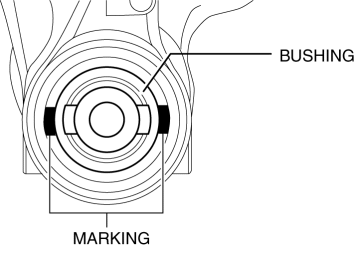
2. Press the rear hub support bushing (rear) out using the SSTs
.
Hub Support Bushing (Rear) Installation Note
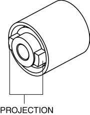
1. Align the projection of a hub support bushing with the marks placed during removal.
2. Install a new hub support bushing (rear) using the SSTs
.
Hub Support Bushing (Front) Installation Note
1. Align the projection of a hub support bushing with the marks placed during removal.
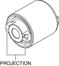
2. Install a new hub support bushing (front) using the SSTs
.
Wheel Hub Bolt Installation Note
1. Install the new wheel hub bolt using a press.
Bolt (Wheel Hub) Installation Note
CAUTION:
-
The wheel hub installation bolts are tightened to a specific angle, but they are not plastic tightening bolts. Accordingly, the bolt length inspection is not needed.
 Wheel Hub Component Inspection
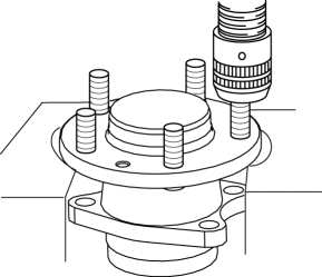
Wheel Bearing Excessive Play Inspection
1. Install the magnetic base and dial gauge as shown in the figure and measure
the wheel bearing axial excessive play.
If it exceeds the maximu ...
 Wheel Hub Component Removal/Installation [Awd]
CAUTION:
Performing the following procedures without first removing the ABS wheel-speed
sensor may possibly cause an open circuit in the wiring harness if it is pulled
by mistake. Befo ...
Other materials:
Decoration Panel Removal/Installation
CAUTION:
Affix protective tape to the position shown in the figure.
1. Disconnect the negative battery cable..
2. Open the glove compartment.
3. Insert a tape-wrapped flathead screwdriver in the position indicated by the
arrow (1) in the figure and detach clip A.
4. ...
Starter Removal/Installation [Skyactiv G 2.0]
WARNING:
Remove and install all parts when the engine is cold, otherwise they can
cause severe burns or serious injury.
When the battery cables are connected, touching the vehicle body with starter
terminal B will generate sparks. This can cause personal injury, fire, and d ...
C Pillar Trim Removal/Installation
1. Disconnect the negative battery cable..
2. Remove the following parts:
a. Trunk board.
b. Trunk end trim.
c. Rear scuff plate.
d. Trunk side trim.
e. D-pillar trim.
3. Partially peel back the seaming welt.
4. Remove the fastener A.
5. Take the shaded area shown in the figure ...
