Mazda CX-5 Service & Repair Manual: Turn Signal/Hazard Warning Indicator Lights
Purpose
-
Notifies the driver that a turn light, the hazard warning lights are flashing.
Function
-
Flashes according to the turn switch and hazard warning switch operations.
Construction
-
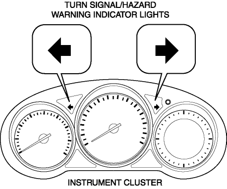
Displayed in the instrument cluster.
Operation
Turn system
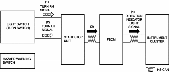
1. When the turn switch is operated to the RH position, a turn RH signal is input to the start stop unit.
2. When the turn switch is operated to the LH position, a turn LH signal is input to the start stop unit.
3. The start stop unit sends the turn RH or LH signal to the front body control module (FBCM).
4. The front body control module (FBCM) sends the turn RH or LH signal to the instrument cluster as a direction indicator light signal.
5. When a direction indicator light signal is received, the instrument cluster flashes the direction indicator light.
Hazard system
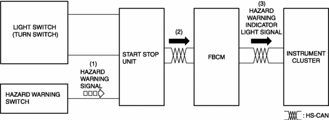
1. When the hazard switch is turned on, a hazard signal is input to the start stop unit.
2. The start stop unit sends a hazard signal to the front body control module (FBCM).
3. The front body control module (FBCM) sends the hazard signal to the instrument cluster as a hazard warning flashing signal.
4. When the hazard warning flash signal is received, the instrument cluster flashes the hazard warning lights.
Fail-safe
-
Function not equipped.
 Turn And Hazard Indicator Alarm
Purpose
The turn and hazard indicator alarm notifies the driver that a turn light
or the hazard warning lights are flashing.
Function
When the instrument cluster receives the tu ...
 Trailer
...
Other materials:
Blind Spot Monitoring (Bsm) Off Switch
Purpose
The blind spot monitoring (BSM) system can be turned on or off optionally
by the driver.
Function
The switch operation signal is sent to the instrument cluster.
Construction
The BSM OFF switch is built into the cluster switch.
The resistance is bui ...
Engine Control System
Outline
L-jetronic*1 and D-jetronic*2 type detectors have been combined for intake
air amount detection, improving the accuracy of the intake air amount measurement.
MAF sensor adopted
MAP sensor adopted
IAT sensor No.1 and No.2 adopted
...
Front Body Control Module (Fbcm) Configuration (Using As Built Data)
NOTE:
If the configuration is performed using As-Built data, the set value of the
personalization function is reset to the initial value (condition when shipped
from factory). Verify the set value with the customer and perform the personalization
function setting after performing th ...
