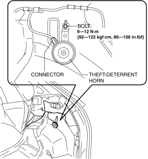
Mazda CX-5 Service & Repair Manual: Theft Deterrent Horn Removal/Installation
1. Disconnect the negative battery cable..
2. Remove the following parts:
a. Trunk end trim.
b. Rear scuff plate (RH).
c. Trunk side trim (RH).
3. Disconnect the connector.

4. Remove the bolt.
5. Remove the theft-deterrent horn.
6. Install in the reverse order of removal.
 Theft Deterrent Horn Inspection
1. Disconnect the negative battery cable..
2. Remove the following parts:
a. Trunk end trim.
b. Rear scuff plate (RH).
c. Trunk side trim (RH).
d. Theft-deterrent horn.
3. Apply battery po ...
Other materials:
Rear Upper Arm Removal/Installation [Awd]
WARNING:
Verify that the crossmember is securely supported by a jack. If the rear
crossmember falls off, it can cause serious injury or death, and damage to the
vehicle.
CAUTION:
Performing the following procedures without first removing the rear ABS wheel-speed
sensor ...
Meters and Gauges
1 Speedometer
2 Odometer, Trip Meter and Trip Meter Selector
3 Tachometer
4 Fuel Gauge
5 Dashboard Illumination
6 Outside Temperature Display
7 Trip Computer and INFO Switch
Speedometer
The speedometer indicates the speed of the vehicle.
Odometer, Trip Meter and Trip Meter Selector
...
Audio Unit Removal/Installation
Removal
1. Disconnect the negative battery cable.
2. Remove the decoration panel..
3. Remove the bolt.
4. Remove the screws.
NOTE:
When removing the audio unit, the audio unit could interfere with the climate
control unit and scratch the climate control unit. Perform the serv ...

