Mazda CX-5 Service & Repair Manual: Start Stop Unit Removal/Installation
CAUTION:
-
If configuration is not performed when the start stop unit is replaced with a new one, the vehicle specification information is not stored in the start stop unit and the system will not operate normally.
-
When performing configuration, it is necessary to read the vehicle specification information from the start stop unit before replacing it. Connect the M-MDS to the vehicle and perform vehicle identification before removing the start stop unit. The vehicle specification information is temporarily stored in the M-MDS.
NOTE:
-
The start stop unit prior to replacement stores the vehicle specification information.
-
A new start stop unit does not store any vehicle specification information.
-
If the vehicle specification information from the start stop unit prior to replacement cannot be read, perform the configuration using As-Built data.
1. When replacing the start stop unit, perform the configuration..
2. Disconnect the negative battery cable..
3. Remove the following parts:
a. Driver-side air bag module.
b. Steering wheel.
c. Clock spring.
d. Column cover.
e. Wiper and washer switch.
f. Light switch.
4. Disconnect the connector.
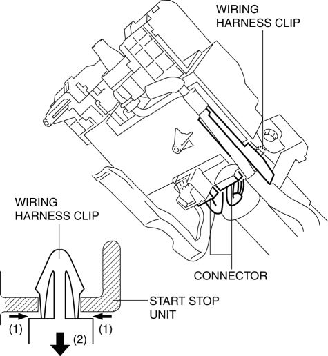
5. While pressing the tabs of the clip in the direction of arrow (1) shown in the figure, press it in the direction of arrow (2) to detach the connector tabs from the start stop unit.
6. Remove the wiring harness clip from the start stop unit.
7. Make a groove on the bolt head by punching it with a chisel using a hammer, and remove the bolts by rotating them counterclockwise.
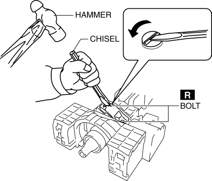
8. Remove the bolts.
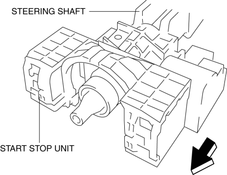
9. Remove the start stop unit from the steering shaft by pulling it in the direction of the arrow shown in the figure.
10. Install in the reverse order of removal..
NOTE:
-
If configuration cannot be performed by reading/writing of the vehicle specification information, perform the configuration using As-Built information after replacing the start stop unit..
Start Stop Unit Installation Note
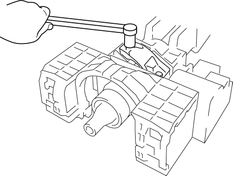
1. Temporarily install the start stop unit to the steering shaft using new start stop unit installation bolts.
2. Tighten the start stop unit installation bolts until the heads break off.
 Start Stop Unit Inspection
1. Remove the following parts:
a. Column cover.
2. Verify that the voltages of each of the terminals are as indicated in the
terminal voltage table (reference).
If the voltage is not as ...
 Throttle Body Inspection
Resistance Inspection
1. Disconnect the negative battery cable..
2. Disconnect the throttle body connector.
3. Measure the resistance between throttle body terminals E and F.
Throttle bo ...
Other materials:
Turn Light System
Purpose
The turn light system flashes the turn light three times automatically according
to the turn switch operation.
The front body control module (FBCM) performs turn light system fail-safe..
Function
The front body control module (FBCM) performs control based on th ...
Power Window System Preliminary Inspection [Power Window System]
Manual Open/Close Function Inspection
STEP
INSPECTION
ACTION
1
Switch the ignition ON (engine off or on).
Operate the power window using the manual open/close function on
the power window main swit ...
Power Seat Switch Inspection
WARNING:
Handling a side air bag improperly can accidentally operate (deploy) the
air bag, which may seriously injure you. Read the service warnings/cautions
in the Workshop Manual before handling the front seat (side air bag integrated)..
1. Switch the ignition off (LOCK).
2. ...
