Mazda CX-5 Service & Repair Manual: Side Member Installation [Panel Replacement]
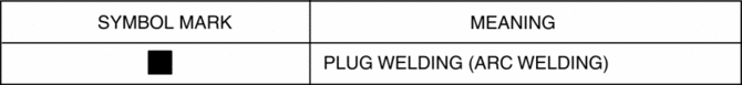
Symbol Mark
Installation Procedure
1. When installing new parts, measure and adjust the body as necessary to conform with standard dimensions.
2. Drill holes for the plug welding before installing the new parts.
3. After temporarily installing new parts, make sure the related parts fit properly.
4. Plug weld the 45 locations shown in the figure, then install the side member.
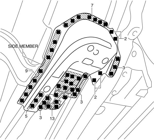

 Side Member Removal [Panel Replacement]
Symbol Mark
Removal Procedure
1. Drill the 45 locations shown in the figure.
NOTE:
When drilling, do not drill a hole all the way through or there could be
a problem when installing ...
Other materials:
Shift Solenoid No.1 [Fw6 A EL, Fw6 Ax EL]
Purpose/Function
Shift solenoid No.1 adjusts the hydraulic pressure in the low clutch circuit
based on the current demand from the TCM according to the vehicle conditions.
Construction
Shift solenoid No.1 is installed to the solenoid control valve body.
Shift solenoid ...
Front Drive Shaft (Double Offset Joint) Disassembly/Assembly
1. Disassemble in the order indicated in the table.
2. Assemble in the reverse order of disassembly.
1
Boot band (transaxle side)
(See FRONT DRIVE SHAFT (TRIPOD JOINT) DISASSEMBLY/ASSEMBLY.)
2
Clip
(See Clip Disassembly Note.)
...
Speedometer
Purpose
The speedometer notifies the driver of the speed at which the vehicle is
traveling.
Function
The instrument cluster controls the speedometer needle based on the vehicle
speed signal from the PCM and displays the current vehicle speed.
Construction
An an ...
