Mazda CX-5 Service & Repair Manual: Rear Washer Hose Removal/Installation
1. Disconnect the negative battery cable..
2. Remove the front over fender..
3. Remove the mudguard (RH)..
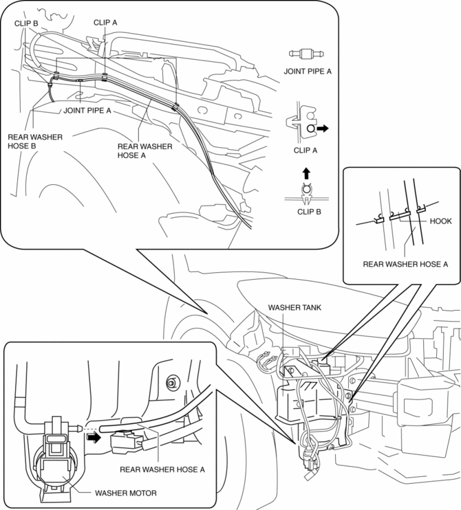
4. Disconnect the rear washer hose A from the washer motor.
5. Remove the rear washer hose A from the washer tank hook.
6. Remove the rear washer hose A from clips A and B.
7. Disconnect the rear washer hose A from the joint pipe A and remove it.
8. Disconnect the rear washer hose B from the joint pipe A.
9. Remove the sunroof seaming welt. (with sunroof).
10. Remove the A pillar trim..
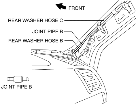
11. Disconnect the rear washer hose B from the joint pipe B and remove it.
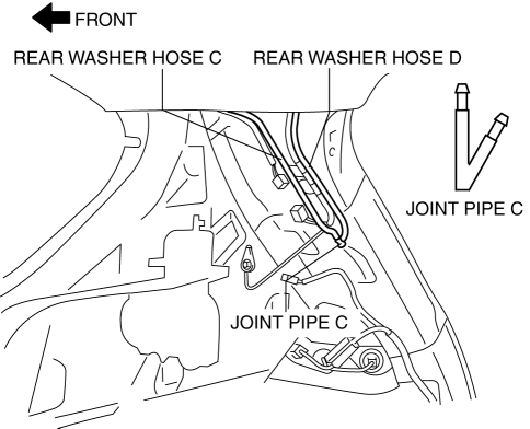
12. Disconnect the rear washer hose C from the joint pipe B.
13. Remove the following parts:
a. Map light.
b. Sunvisor.
c. Front scuff plate.
d. Rear scuff plate.
e. B-pillar lower trim.
f. Front seat belt adjusting cover.
g. Front seat belt upper anchor installation bolt.
h. B-pillar upper trim.
i. Assist handle.
j. Trunk board.
k. Trunk end trim.
l. Trunk side trim.
m. D-pillar trim.
n. C-pillar trim.
o. Headliner.
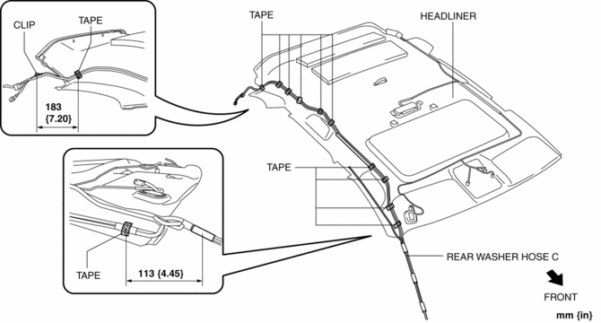
14. Remove the tape and clips shown in the figure.
Without sunroof
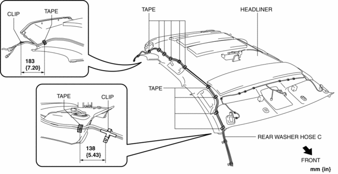
With sunroof
15. Disconnect the rear washer hose C from the joint pipe C and remove it.
16. Disconnect the rear washer hose D from the joint pipe C.
17. Remove the liftgate upper trim..
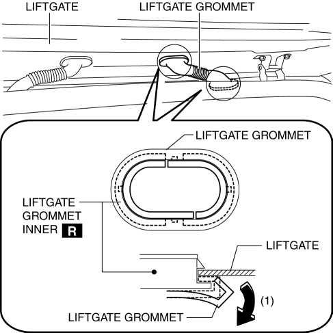
18. Partially peel the liftgate grommet in the direction of arrow (1) shown in the figure, and remove the liftgate grommet from the liftgate grommet inner.
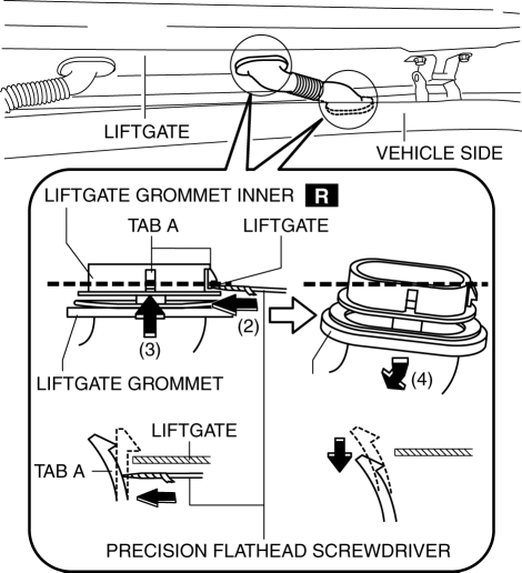
19. Using a tape-wrapped precision flathead screwdriver, press the liftgate grommet inner tabs in the directions of arrows (2) and (3) shown in the figure and remove each liftgate grommet inner from the liftgate and vehicle side in the direction of arrow (4).
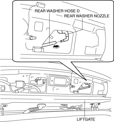
20. Disconnect the rear washer hose D from the rear washer nozzle and remove it.
21. Install in the reverse order of removal.
 Washers
...
 Rear Washer Nozzle Adjustment
CAUTION:
If the nozzle angle is adjusted with excessive force by strongly inserting
a needle or similar thin tool into the injection nozzle of rear washer nozzle,
it could damage the noz ...
Other materials:
Front Door Latch And Lock Actuator Removal/Installation
1. Perform the front door glass preparation..
2. Disconnect the negative battery cable..
3. Remove the following parts:
a. Inner garnish.
b. Front door trim.
c. Inner handle.
d. Front door glass.
e. Front door module panel.
f. Front door key cylinder.
4. Remove the door lock knob c ...
Front Seat Belt Pretensioner and Load Limiting Systems
For optimum protection, the driver and front passenger seat belts are equipped
with pretensioner and load limiting systems. For both these systems to work properly
you must wear the seat belt properly.
Pretensioners:
In moderate or severe frontal or nearfrontal accidents, the front air bag and ...
Oil Shower Pipe
Outline
Mechanical resistance loss has been reduced through structural changes to
achieve optimum fuel economy. An oil shower pipe has been adopted as a part
of this structural change.
Purpose, Function
The oil shower pipe injects engine oil to lubricate the contact points ...
