Mazda CX-5 Service & Repair Manual: Rear Seat Back Trim Removal/Installation
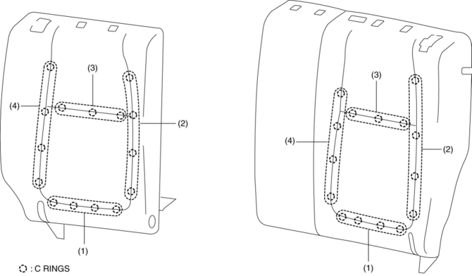
6:4 Split Type
1. Remove the trunk board..
2. Remove the rear seat back..
3. Remove the headrest.
4. Remove the rear seat back frame..
5. Remove the C rings in the order of (1), (2), (3), and (4) shown in the figure, and remove the rear seat back trim from the rear seat back pad.

CAUTION:
-
If a damaged C rings are reused, it may not be possible to install the rear seat back trim and rear seat back pad correctly. When removing and installing C rings, be careful not to damage them.
-
If a C rings are damaged, replace the C rings with a new one.
6. Install in the reverse order of removal.
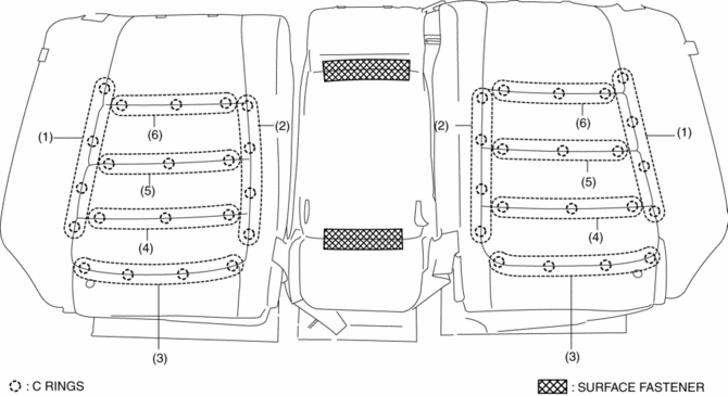
4:2:4 Split Type
1. Remove the trunk board..
2. Remove the rear seat..
3. Remove the rear seat back..
4. Remove the headrest.
5. Remove the rear seat back frame..
6. Partially peal back the rear seat back trim from the rear seat back pad, remove C rings in the order of (1), (2), (3), (4), (5), (6) shown in the figure. (LH/RH)

CAUTION:
-
If a damaged C rings are reused, it may not be possible to install the rear seat back trim and rear seat back pad correctly. When removing and installing C rings, be careful not to damage them.
-
If a C rings are damaged, replace the C rings with a new one.
7. Remove the surface fasteners while peeling back the rear seat back trim, and remove the rear seat back trim from the rear seat back pad. (CENTER)
8. Install in the reverse order of removal.
 Rear Seat Back Striker Removal/Installation
1. Disconnect the negative battery cable..
2. Press the push knob to fold the rear seat back.
3. Remove the following parts:
a. Trunk board.
b. Trunk end trim.
c. Rear scuff plate.
d. Trun ...
 Rear Seat Center Armrest Removal/Installation
1. Operate the push knob (RH) and lower the rear seat back (RH).
2. Remove screw A.
3. Remove the rear seat center armrest hinge cover (RH) in the direction of the
arrow (1) shown in the fig ...
Other materials:
Tire Pressure Monitoring System Warning Light
Purpose, Function
The tire pressure monitoring system warning light notifies the driver that
it was determined that a tire pressure has decreased below the specified value
based on the initialization.
The tire pressure monitoring system warning light notifies the driver that
...
Refrigerant Pressure Sensor Removal/Installation [Manual Air Conditioner]
1. Disconnect the negative battery cable..
2. Discharge the refrigerant..
3. Disconnect the refrigerant pressure sensor connector.
CAUTION:
If moisture or foreign material enters the refrigeration cycle, cooling ability
will be lowered and abnormal noise will occur. Always immediate ...
Electrical System
Electrical Parts
Battery cable
Before disconnecting connectors or removing electrical parts, disconnect
the negative battery cable.
Wiring Harness
To remove the wiring harness from the clip in the engine room, pry up the
hook of the clip using a flathead screwdriver. ...
