
Mazda CX-5 Service & Repair Manual: Rear Map Light
Purpose
-
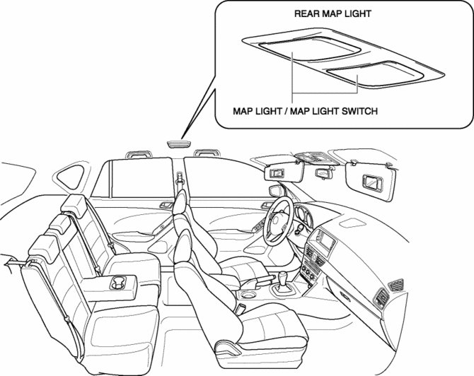
The rear map lights shine light at the center of the vehicle interior.
Function
-
The rear map lights illuminate when the interior light switch is in the ON position or the map light switch is turned on.
-
The rear map lights illuminate according to the lock condition of the driver's door and open/close conditions of the doors under the rear body control module (RBCM) control when the interior light switch for front map lights is in the DOOR position.
Construction
-
The rear map lights are assembled to the headliner.
Operation
Map light switch operation
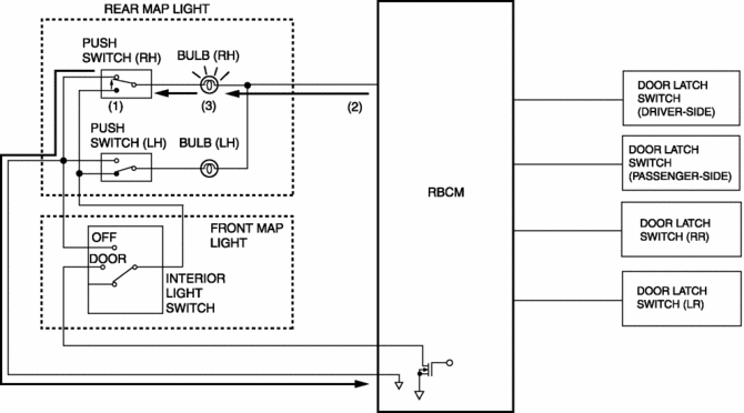
1. The map light switch is on.
2. The battery current flows to the map light bulb from the rear body control module (RBCM).
3. The map light illuminates.
Interior light switch for front map lights operation
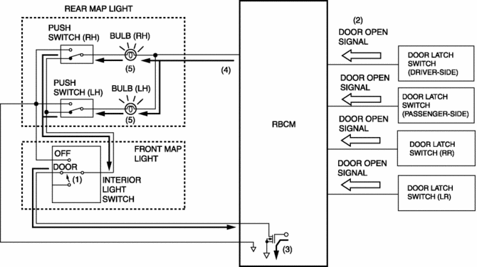
1. Interior light switch for the front map lights is in the DOOR position.
2. When any door is opened, the door open signal is input to the rear body control module (RBCM).
3. When the rear body control module (RBCM) receives the door-open signal, it turns on the transistor.
4. When the transistor turns on, the battery current flows to the map light bulb from the rear body control module (RBCM).
5. The map light illuminates.
NOTE:
-
When the interior light switch is in the DOOR position, the map light illumination on/off timing is controlled by the interior light control system. For details, refer to the interior light control system..
Fail-safe
-
Function not equipped.
 Map Light Removal/Installation
Front Map Light
1. Disconnect the negative battery cable..
2. Open the sunglasses holder.
3. Remove the screws from the front map light.
4. Move the front map light in the direction of the ...
 Room Light Control System
Outline
The room light control system changes the illumination condition and illumination
level of the interior lights (door position) according to whether the doors
are opened/closed and ...
Other materials:
Power Window System Preliminary Inspection [Power Window System]
Manual Open/Close Function Inspection
STEP
INSPECTION
ACTION
1
Switch the ignition ON (engine off or on).
Operate the power window using the manual open/close function on
the power window main swit ...
Charging System Warning Light [Skyactiv G 2.0]
Purpose, Function
Warns the driver of a charging system malfunction.
Construction
The charging system warning light is built into the instrument cluster..
Operation
Illuminates when a malfunction occurs in the charging system and DTCs is
stored in the PCM.
...
Column Cover Removal/Installation
1. Pull down the steering wheel.
2. Press the shaded area shown in the figure using your thumb, and lift the upper
column cover in the direction of arrow (1).
3. Pull the upper column cover in the direction of the arrow (2) and remove it
while detaching pins A, tabs B and guides C.
4. ...
