Mazda CX-5 Service & Repair Manual: Map Light Removal/Installation
Front Map Light
1. Disconnect the negative battery cable..
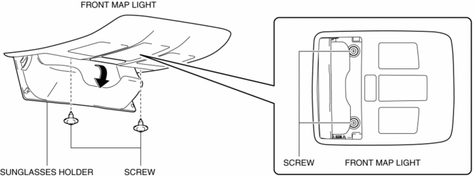
2. Open the sunglasses holder.
3. Remove the screws from the front map light.
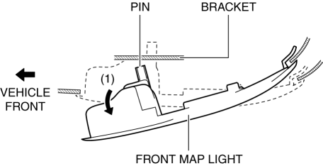
4. Move the front map light in the direction of the arrow (1) shown in the figure and pull out the pin from the bracket.
CAUTION:
-
Be careful not to pull the connector out strongly when removing the front map light. Otherwise, the contact surface of the wiring harness secured to the headliner will come off and the wiring harness could be pulled out. If the front map light is installed with the wiring harness pulled out, the wiring harness could get caught between the headliner and front map light bracket resulting in an open or short circuit in the wiring harness.
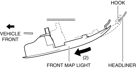
5. Move the front map light in the direction of the arrow (2) shown in the figure and pull out the front map light from the headliner.
6. Disconnect the connector.
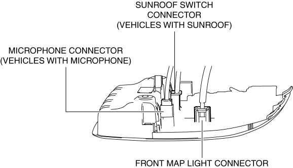
7. Remove the front map light.
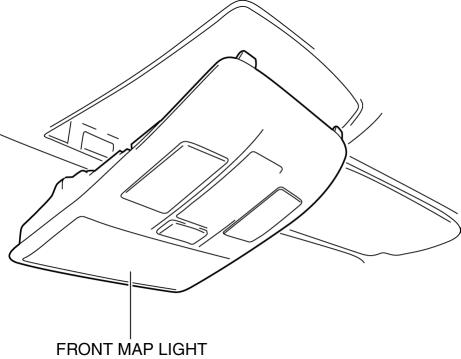
8. Install in the reverse order of removal.
Rear Map Light
1. Disconnect the negative battery cable..
2. Remove the following parts:
a. Sunroof seaming welt (vehicles with sunroof).
b. A-pillar trim.
c. Sunvisor.
d. Front scuff plate.
e. Rear scuff plate.
f. B-pillar lower trim.
g. Adjust anchor cover.
h. Upper anchor installation bolt on the seat belt.
i. B-pillar upper trim.
j. Assist handle.
k. Trunk board.
l. Trunk end trim.
m. Trunk side trim.
n. D-pillar trim.
o. C-pillar trim.
p. Headliner.
3. Disconnect the connector.
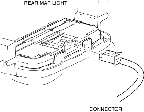
4. Move the bracket in the direction of the arrow (1) shown in the figure, press the rear map light in the direction of the arrow (2) shown in the figure, and detach the rear map light tab and bracket.
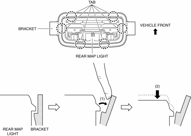
5. Detach all the rear map light tabs and bracket and remove the rear map light from the bracket.
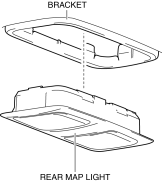
CAUTION:
-
If the rear map light is removed from the bracket, the rear map light may fall off and be damaged. When removing the rear map light from the bracket, hold the rear map light on the lens side with a hand during servicing.
6. Install in the reverse order of removal.
 Map Light Inspection
Front Map Light
1. Disconnect the negative battery cable..
2. Remove the front map light..
3. Verify that the continuity between the front map light terminals is as indicated
in the table.
...
 Rear Map Light
Purpose
The rear map lights shine light at the center of the vehicle interior.
Function
The rear map lights illuminate when the interior light switch is in the ON
position or th ...
Other materials:
Driving on Uneven Road
Your vehicle's suspension and underbody can be damaged if driven on rough/uneven
roads or over speed bumps at excessive speeds. Use care and reduce speed when traveling
on rough/uneven roads or over speed bumps.
Use care not to damage the vehicle's underbody, bumpers or muffler(s) when ...
Front Pillar Installation [Panel Replacement]
Symbol Mark
Installation Procedure
1. When installing new parts, measure and adjust the body as necessary to conform
with standard dimensions.
2. Drill holes for the plug welding before installing the new parts.
3. After temporarily installing new parts, make sure the related parts fit p ...
Front Fog Light Switch Inspection
1. Disconnect the negative battery cable..
2. Remove the column cover..
3. Remove the light switch..
4. Verify that the continuity between the light switch terminals is as indicated
in the table.
If not as indicated in the table, replace the light switch.
...
