
Mazda CX-5 Service & Repair Manual: Rear Door Trim Removal/Installation
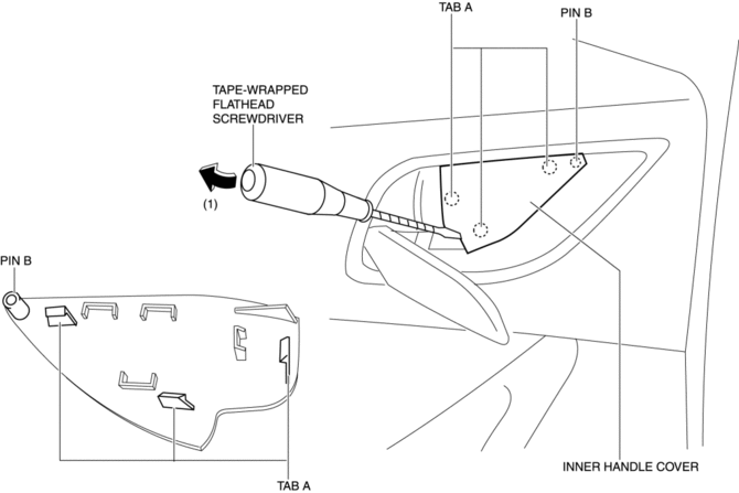
1. Insert a tape-wrapped flathead screwdriver in the position indicated by the arrow (1) in the figure and remove the inner handle cover while detach tabs A, pin B.
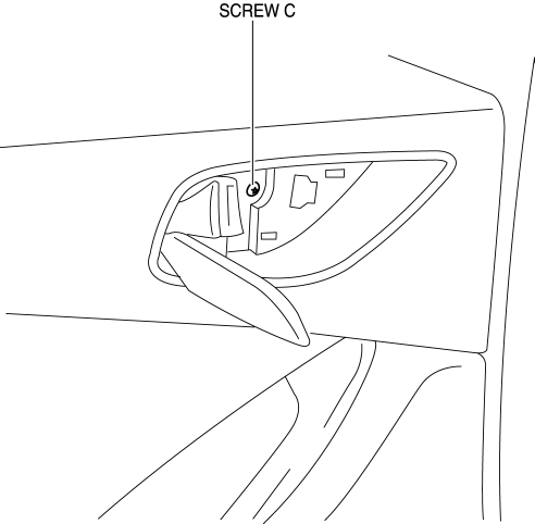
2. Remove the screw C.
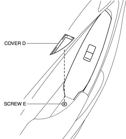
3. Remove the cover D, then remove the screw E.
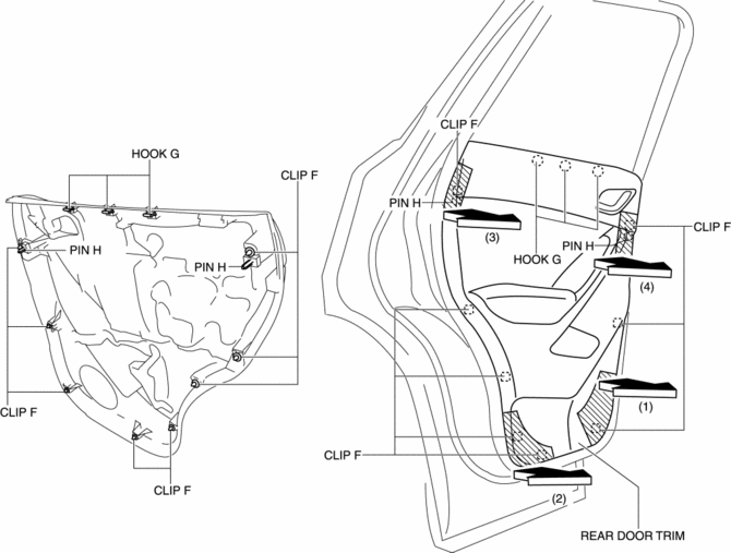
4. Take the shaded area shown in the figure, and pull the rear door trim in the direction of the arrow in the order of (1), (2), (3), (4) while detaching clips F, hooks G and pin H.
CAUTION:
-
If the rear door trim is removed in the same way as past vehicles by pulling it upward, it could damage clips F, hooks G and pins H. When removing the rear door trim, always pull it in the direction of the arrow shown in the figure.
5. Remove the tab I in the direction of the arrow (5) shown in the figure.
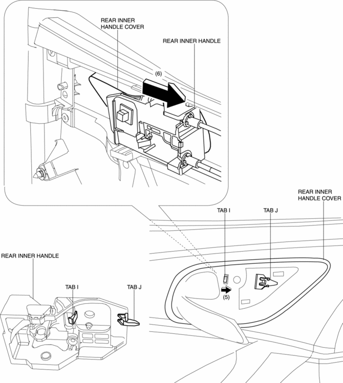
6. Remove the rear inner handle in the direction of the arrow (6) shown in the figure while detaching the tab J.
7. Disconnect the power window subswitch connector.
8. Install in the reverse order of removal.
 Rear Door Trim Disassembly/Assembly
1. Disassemble in the order shown in the figure.
1
Switch panel cover
2
Power window subswitch.
3
Fastener
...

Other materials:
Side Air Bag Sensor Removal/Installation [Two Step Deployment Control System]
WARNING:
Handling the side air bag sensor improperly can accidentally operate (deploy)
the air bag module, which may seriously injure you. Read the air bag system
service warnings and cautions before handling the side air bag sensor..
1. Switch the ignition to off.
2. Disconnec ...
Electrical System
Electrical Parts
Battery cable
Before disconnecting connectors or removing electrical parts, disconnect
the negative battery cable.
Wiring Harness
To remove the wiring harness from the clip in the engine room, pry up the
hook of the clip using a flathead screwdriver. ...
Map Light Bulb Removal/Installation
Front Map Light
1. Disconnect the negative battery cable..
2. To prevent scratches or damage, affix protective tape to the position shown
in the figure.
CAUTION:
If a flathead screwdriver is inserted into the gap between the front map
light and lens, the front map light could inter ...
