Mazda CX-5 Service & Repair Manual: Rear Combination Light Removal/Installation
NOTE:
-
Fogging or condensation on the inside of the rear combination lights may occur due to a natural phenomenon occurring as a result of a temperature difference between the interior and exterior of the combination lights. However, it has no effect on the light performance because the temperature inside the rear combination lights rises after illuminating the brake/taillight bulbs or a period of time has elapsed.
1. Disconnect the negative battery cable..
2. Insert a tape-wrapped flathead screwdriver into the service hole in the position shown in the figure.
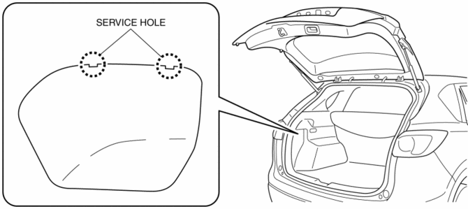
3. Move the flathead screwdriver in the direction of the arrow (1) shown in the figure, pull out the service hole cover, and detach the service hole cover tab and trunk side trim.
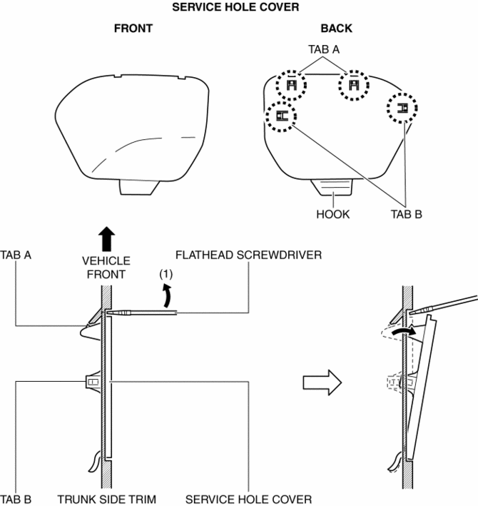
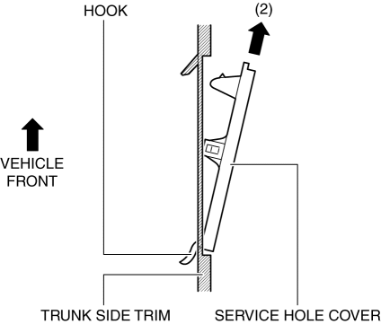
4. Pull out the service hole cover in the direction of the arrow (2) shown in the figure and pull out the service hole cover hook from the trunk side trim.
5. Remove the service hole cover.
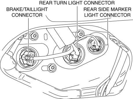
6. Disconnect the connectors.
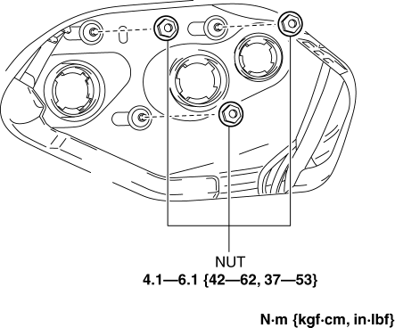
7. Remove the nuts.
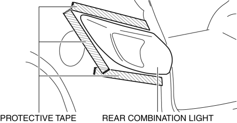
8. To prevent scratches or damage, affix protective tape to the position shown in the figure.
CAUTION:
-
When the rear combination light is removed from the body, perform the procedure after affixing protective tape to the body. Otherwise, the body could interfere with the rear combination light and cause scratching or damage to the body.
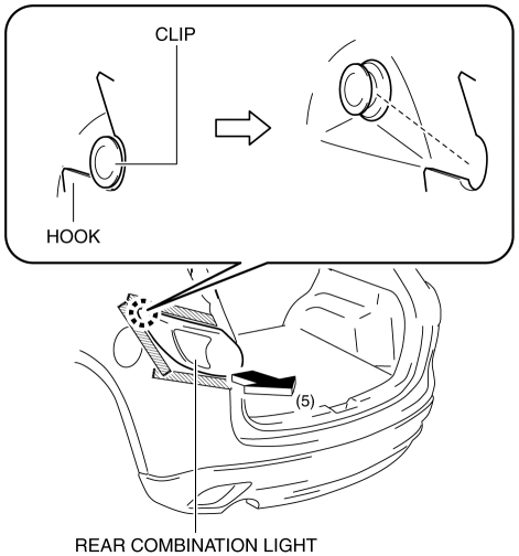
9. Pull the rear combination light in the direction of the arrow (5) shown in the figure and remove the rear combination light hook from the clip.
10. Pull out the rear combination light pin.
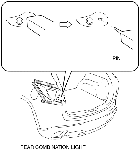
11. Remove the rear combination light.
12. Install in the reverse order of removal.
 Rear Combination Light
Purpose
The rear combination lights are used to signal the following conditions to
vehicles/people at the rear.
Rear turn lights: Signals a left or right turn of the vehicle.
...
 Rear Side Marker Light Bulb Removal/Installation
1. Disconnect the negative battery cable..
2. Insert a tape-wrapped flathead screwdriver into the service hole in the position
shown in the figure.
3. Move the flathead screwdriver in the di ...
Other materials:
Front Seat Belt Pretensioner and Load Limiting Systems
For optimum protection, the driver and front passenger seat belts are equipped
with pretensioner and load limiting systems. For both these systems to work properly
you must wear the seat belt properly.
Pretensioners:
In moderate or severe frontal or nearfrontal accidents, the front air bag and ...
Fuel-Filler Lid and Cap
WARNING
When removing the fuel-filler cap, loosen the cap slightly and wait for any hissing
to stop. Then remove it:
Fuel spray is dangerous. Fuel can burn skin and eyes and cause illness if ingested.
Fuel spray is released when there is pressure in the fuel tank and the fuel-filler
cap is r ...
Cargo Compartment Light Bulb Removal/Installation
1. Disconnect the negative battery cable..
CAUTION:
Always disconnect the negative battery cable before performing the cargo
compartment light bulb removal. Otherwise, the circuit may be shorted resulting
in damage to the related parts such as the rear body control module (RBCM).
...
