Mazda CX-5 Service & Repair Manual: Panel Light
Purpose
-
The panel light adjusts the instrument cluster and steering switch illumination brightness.
Function
-
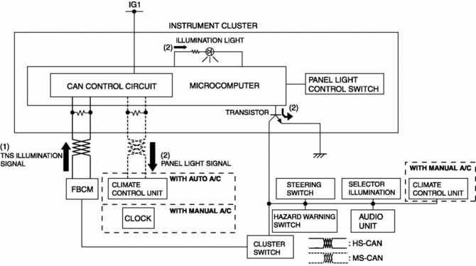
The instrument cluster adjusts the brightness of the following illumination lights when a TNS illumination signal sent via CAN transmission from the front body control module (FBCM) is received.
-
Instrument cluster
-
Climate control unit
-
Steering switch
-
Cluster switch
-
Hazard warning switch
-
Selector illumination
-
Audio unit
-
Clock (with manual A/C)
-
The instrument cluster changes the brightness of the illumination lights according to the rotation signal of the panel light control switch.
Construction
-
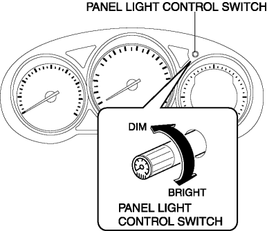
The panel light control switch is set in the instrument cluster.
Operation
-
When the ignition is switched ON (engine off or on), the instrument cluster receives (1) the TNS illumination signal from the front body control module (FBCM).
-
The instrument cluster performs the following controls when it receives the TNS illumination signal.
-
Changes the brightness of the instrument panel illumination.
-
Outputs a panel light signal via CAN signal to the climate control unit (with auto A/C)/clock (with manual A/C).
-
Turns on the panel light circuit transistor.
-
When the transistor turns on, a ground circuit with the panel light is established and the panel light illuminates.
Panel light control switch operation
-
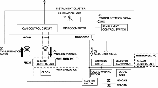
When the ignition is switched ON (engine off or on), the instrument cluster receives (1) the TNS illumination signal from the front body control module (FBCM).
-
The instrument cluster changes the brightness of the panel light according to the rotation angle when it receives a panel light control switch rotation signal while receiving the TNS illumination signal.
-
The instrument cluster outputs a panel light signal to related units.
Fail-safe
-
Function not equipped.
 PID/Data Monitor Inspection [Instrument Cluster]
1. Connect the M-MDS to the DLC-2.
2. After the vehicle is identified, select the following items from the initialization
screen of the M-MDS.
a. Select “DataLogger”.
b. Select “Modulesâ ...
 Gauges
...
Other materials:
Direct Fuel Injection System
Purpose, Outline
Engine output has been improved through the direct injection of fuel into
the combustion chamber.
High response can be because there is no time lag from when the fuel injection
starts until the fuel is provided to the combustion chamber.
Structure
...
Extractor Chamber Removal/Installation
1. Disconnect the negative battery cable..
2. Remove the following parts:
a. Rear splash shield.
b. Rear combination light.
c. Rear bumper.
3. Insert a tape-wrapped flathead screwdriver shown in the figure and remove
clips in the direction of arrow (1).
4. Remove the extractor cham ...
Blind Spot Monitoring (Bsm) Off Indicator Light
Purpose
The BSM OFF indicator light informs the driver that the Blind Spot Monitoring
(BSM) system is turned off or there is a malfunction in the system.
Function
The instrument cluster illuminates the BSM OFF indicator light based on the
BSM system off signal sent via a CA ...
