Mazda CX-5 Service & Repair Manual: Magnetic Clutch Disassembly/Assembly [Manual Air Conditioner]
1. Disassemble in the order indicated in the table.
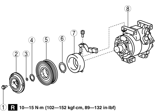
|
1 |
Bolt (See Bolt Removal/Installation Note.) |
|
2 |
Pressure plate |
|
3 |
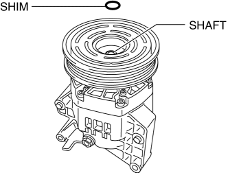
Shim (See Shim Installation Note.) |
|
4 |
Snap ring (See Snap Ring Removal/Installation Note.) |
|
5 |
A/C compressor pulley |
|
6 |
Snap ring (See Snap Ring Removal/Installation Note.) |
|
7 |
Stator |
|
8 |
A/C compressor body |
2. Assemble in the reverse order of disassembly.
3. Adjust the magnetic clutch clearance..
Bolt Removal/Installation Note
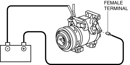
1. When removing or installing the bolt, lock the A/C compressor pulley against rotation using the following procedure.
CAUTION:
-
When connecting the positive battery cable to the magnetic clutch connector, use a cable with a female terminal of the correct size. Otherwise, load will be applied to the terminal, resulting in deformation or damage, and poor contact. In addition, the positive battery cable could disconnect from the connector resulting in a short circuit.
a. Apply battery positive voltage to the magnetic clutch terminal and connect the A/C compressor body to the ground.
b. Wrap the drive belt, which is no longer of use, tightly around the A/C compressor pulley.
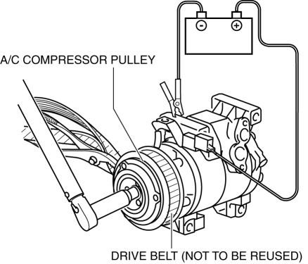
c. Hold the drive belt in place with pliers.
d. Remove/installation the bolt.
-
Tightening torque
-
10—15 N·m {102 —152 kgf·cm, 89 — 132 in·lbf}
2. When installing a new A/C compressor body, replace the recommended bolt.
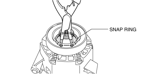
Snap Ring Removal/Installation Note
1. Remove/install the snap ring using a snap ring pliers.
Shim Installation Note
1. First, insert the 1mm (0.039 in)
thick shim into the shaft.
 Magnetic Clutch Disassembly/Assembly [Full Auto Air Conditioner]
1. Disassemble in the order indicated in the table.
1
Bolt
(See Bolt Removal/Installation Note.)
2
Pressure plate
3
...
 Magnetic Clutch Inspection [Full Auto Air Conditioner]
1. Connect battery to terminal A of magnetic clutch and ground to A/C compressor
body.
2. Verify that the magnetic clutch operates.
If there is any malfunction, replace the magnetic cl ...
Other materials:
Bluetooth® Hands-Free
Making a Call
Phonebook Usage
Make a call by saying the contact name in the downloaded phonebook.
Telephone calls can be made by saying the name of a person whose phone number
has been registered in Bluetooth® Hands-Free in advance. Refer to Import contact
(Download Phonebook).
1. Press the ...
Liftgate Latch And Lock Actuator Inspection
The following actuator and switch are integrated with the liftgate latch
and lock actuator.
From the actuator/switch name and operation in the following table, select
the actuator or switch to be inspected, and perform the inspection following
the inspection procedure desc ...
Shroud Upper Reinforcement Installation [Panel Replacement]
Symbol Mark
Installation Procedure
1. When installing new parts, measure and adjust the body as necessary to conform
with standard dimensions.
2. Drill holes for the plug welding before installing the new parts.
3. After temporarily installing new parts, make sure the related parts fit p ...
