Mazda CX-5 Service & Repair Manual: Headlight Leveling Actuator
Purpose, Function
-
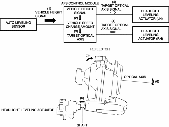
The headlight leveling actuator drives the motor based on the target optical axis voltage, which is input from the AFS control module, to change the optical axis of the headlights.
Construction
-
Built into the front combination lights.
-
Consists of a motor which expands/retracts the shaft, a shaft, and a microcomputer which calculates the shaft expansion/contraction amount.

Operation
1. When the ignition is switched on (engine on or off), the auto leveling sensor inputs a vehicle height signal to the AFS control module.
2. When the headlights (LO) turn on, the AFS control module calculates the amount of change in vehicle height * based on the vehicle height signal.
3. If the operation conditions are met, the AFS control module calculates a target optical axis based on the calculated change in vehicle height *. For details on the operation conditions, refer to the headlight auto leveling system..
4. The AFS control module outputs the calculated target optical axis signal to the headlight leveling actuator.
5. The headlight leveling actuator drives the motor based on the input target optical axis.
6. When the motor is driven, the shaft moves back and forth and the reflector shifts to move the optical axis.

* The amount of change in vehicle height is the calculated 1 s average value of the detected vehicle body angle which the AFS control module detects every 0.1 s.
Fail-safe
-
Function not equipped.
 Headlight High Beam Indicator Light
Purpose
Notifies the user that the headlights (HI) are illuminated.
Function
Illuminates when the headlight (HI) or parking illumination conditions are
met.
Construction
...
 High Mount Brake Light
Purpose
The high-mount brake light signals vehicles to the rear that the vehicle
is stopped.
Function
The high-mount brake light illuminates in conjunction with the operation
...
Other materials:
Power Outer Mirror System
Outline
Power outer mirrors which can be operated remotely have been adopted.
Structural view
System wiring diagram
Function
Mirror glass adjustment function
Outer mirror glass can be adjusted up/down and left/right electrically.
Operation
Mirror glass adjustmen ...
Lap Pre Tensioner Seat Belt [Two Step Deployment Control System]
Purpose
The lap pre-tensioner seat belts retract and tighten the seat belt webbing
to protect the front passengers during a collision.
Function
The lap pre-tensioner seat belts operate (deploy) based on the operation
signal from the SAS control module to instantly retract a ...
Knee Bolster Removal/Installation
1. Disconnect the negative battery cable..
2. Remove the following parts:
a. Driver-side front scuff plate.
b. Driver-side front side trim.
c. Switch panel.
d. Decoration panel.
e. Shift lever knob (MTX).
f. Front console box.
g. Shift panel.
h. Upper panel.
i. Rear console.
j. ...
