Mazda CX-5 Service & Repair Manual: Front Suspension
Outline
-
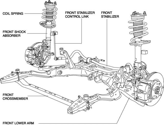
A strut type front suspension has been adopted.
-
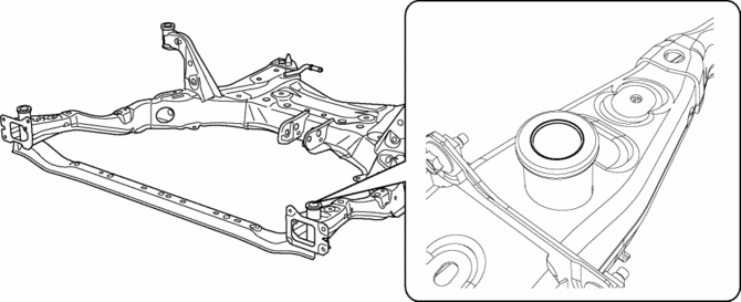
The connection area of the front crossmember and body is a 6-point rigid mount type.
-
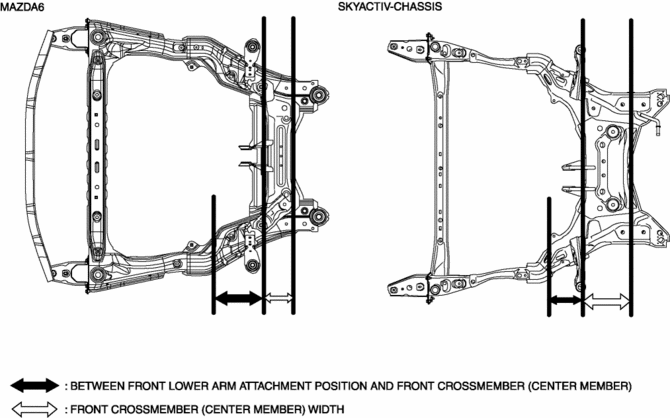
The cross-section on the center member of the front crossmember has been expanded and the longitudinal offset of the front lower arm installation position reduced to realize an optimized framework.
-
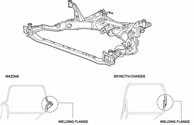
For the front crossmember, the welded part of the flange has been eliminated (flange-less), the cross-section expanded and the connection rigidity of the welded parts improved to achieve both rigidity and light weight.
-
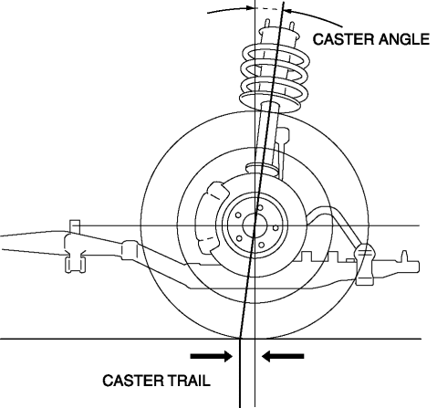
The caster angle and caster trail of the front suspension have been increased.
Structural view
 Front Stabilizer Removal/Installation
CAUTION:
Performing the following procedures without first removing the front ABS
wheel-speed sensor may possibly cause an open circuit in the wiring harness
if it is pulled by mistake ...
 Front Wheel Hub Bolt Replacement
1. Remove the brake calliper component from the steering knuckle and suspend
it out of the way using a cable.
2. Remove the disc plate.
3. Remove the wheel hub bolt using the SST as shown in the ...
Other materials:
Air Mix Actuator [Full Auto Air Conditioner]
Purpose
The air mix actuator moves the air mix door in the A/C unit to adjust the
temperature of the air blown from the air vent.
Function
Door open/close function
The air mix actuator drives the motor based on the signals from the climate
control unit and moves the air mi ...
Automatic Transaxle Fluid (ATF) Adjustment [Fw6 A EL, Fw6 Ax EL]
CAUTION:
Only adjust the ATF level when the ATF temperature is 45—55 °C {113—131 °F}.
If the ATF level is incorrect, it could damage the transaxle.
Do not add ATF over the specification. Otherwise, the transaxle performance
could be reduced and ATF could leak.
1. Re ...
Hydraulic Variable Valve Timing Control
Outline
Changes the exhaust valve timing according to engine operation conditions
to improve engine output, fuel economy, and emission performance.
Based on each input signal, the PCM determines the optimum exhaust valve
timing according to the engine operation conditions. The P ...
