Mazda CX-5 Service & Repair Manual: Front Shock Absorber And Coil Spring Disassembly/Assembly
WARNING:
-
Removing/installing the front shock absorber and coil spring is dangerous. The front shock absorber and coil spring could fly off and cause serious injury or death, and damage the vehicle.
1. Remove the front shock absorber and coil spring..
2. Remove in the order indicated in the table.
3. Install in the reverse order of removal.
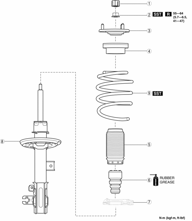
|
1 |
Cap |
|
2 |
Piston rod nut (See Piston Rod Nut Removal Note.) |
|
3 |
Mounting rubber (See Mounting Rubber Installation Note.) |
|
4 |
Bearing |
|
5 |
Dust boot |
|
6 |
Bound stopper |
|
7 |
Lower spring seat |
|
8 |
Front shock absorber |
|
9 |
Coil spring (See Coil Spring Installation Note.) |
Piston Rod Nut Removal Note
WARNING:
-
Before removing the piston rod nut, secure the front shock absorber and coil spring in the SST. Otherwise, the coil spring could fly off under tremendous pressure and cause serious injury or death, or damage to vehicle parts.
1. Install the front shock absorber and coil spring to the SST
according to the following procedures.
NOTE:
-
Install the SST
using a clean rag to prevent the coil spring from being scratched.
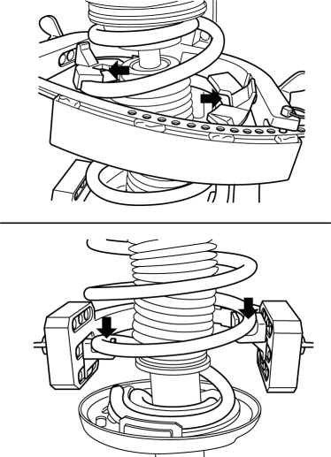
a. Set the SST
attachments (tabs) to the positions shown in the figure.
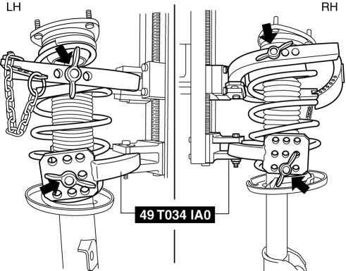
b. Install the front shock absorber and coil spring to the SST
so that the coil spring is set to the position shown in the figure.
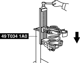
2. Compress the coil spring using the SST
.
3. Remove the piston rod nut.
Coil Spring Installation Note
1. Compress the coil spring using the SST
.
2. Install the front shock absorber so that the lower end of the coil spring is seated on the step of the lower spring seat.
Mounting Rubber Installation Note
1. Install the mounting rubber so that the mounting rubber stud and the front shock absorber bracket are in position A shown in the following figure.
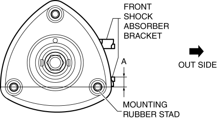
-
A: 0°±5°
 Front Lower Arm Removal/Installation
1. Remove the front under cover No.2..
2. Remove in the order indicated in the table.
3. Install in the reverse order of removal.
4. Inspect the wheel alignment and adjust it if necessary..
...
 Front Shock Absorber And Coil Spring Removal/Installation
CAUTION:
Performing the following procedures without first removing the front ABS
wheel-speed sensor may possibly cause an open circuit in the wiring harness
if it is pulled by mistake ...
Other materials:
Engine Coolant Temperature (ECT) Sensor
Purpose/Function
Detects the ECT as basic information for mainly determining the fuel injection
amount.
Detects the ECT and inputs it to the PCM as an ECT signal.
The ECT sensor No.2 is only used for OBD.
Construction
ECT sensor No.1
Installed to the water out ...
Shift Lock System [Fw6 A EL, Fw6 Ax EL]
Purpose, Function
The shift-lock system operates when the ignition is switched to ON and the
brake pedal is not depressed, and inhibits the selector lever from being shifted
from the P position to other positions.
If the shift-lock cannot be released by the normal operation, it ...
Fuel-Filler Lid and Cap
WARNING
When removing the fuel-filler cap, loosen the cap slightly and wait for any hissing
to stop. Then remove it:
Fuel spray is dangerous. Fuel can burn skin and eyes and cause illness if ingested.
Fuel spray is released when there is pressure in the fuel tank and the fuel-filler
cap is r ...
