
Mazda CX-5 Service & Repair Manual: Dynamic Stability Control (DSC)
Outline
-
Electrical brake assist control has been adopted, improving safety.
-
The DSC HU/CM, integrating both the hydraulic unit (HU) and control module (CM), has been adopted, resulting in a size and weight reduction.
-
An enhanced malfunction diagnosis system, used with the Mazda Modular Diagnostic System (M-MDS), improving serviceability.
-
Serviceability improved by the automatic configuration function.
-
Receives the lateral-G, longitudinal-G, and yaw rate signals between the sophisticated air bag sensor (SAS) control module and the DSC HU/CM via controller area network (CAN) lines instead of the conventional combined sensor.
-
The hill launch assist (HLA), roll over mitigation (ROM), and tire pressure monitoring system (TPMS) have been adopted, improving safety.
DSC operation outline
-
The ABS prevents wheel lock-up during braking. The TCS detects drive wheel spin due to the accelerator pedal being pressed too hard or similar causes and controls engine speed to suppress wheel spin. With these systems, safety is assured when driving or stopping.
-
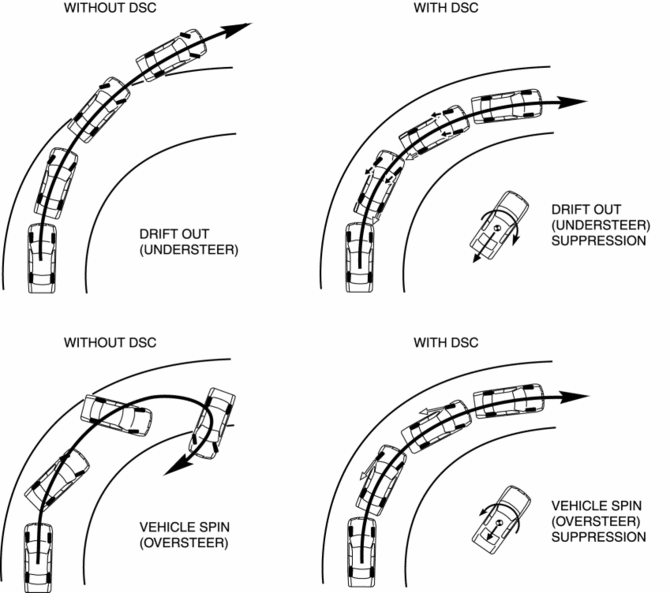
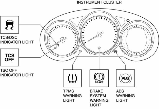
Additionally, sudden changes in vehicle attitude, due to evasive steering or road conditions, are controlled by the DSC. The DSC suppresses vehicle sideslip when driving due to vehicle spin (oversteer) or drift-out (understeer) by controlling braking and engine speed. At this time, the TCS/DSC indicator light illuminates to alert the driver that the DSC is operating due to a dangerous situation. As a result, the driver can calmly react and is provided leeway for the next maneuver, resulting in safe driving conditions.
-
In this way the combination of DSC + ABS + TCS ensures driving, stopping and turning safety in all aspects.
Results of DSC operation
CAUTION:
-
While the DSC is a steering safety system, it does not improve normal steering function. Therefore, always drive carefully, even if the vehicle has DSC, and do not overestimate the DSC capability.
-
If the initialization procedures for the brake fluid pressure, low-G, and yaw rate sensors are not performed correctly, an incorrectly determined initial point may cause a discrepancy between the actual driving conditions of the vehicle and the signals from the sensors, resulting in improper DSC operation. Therefore, after replacing or removing the following parts, make sure to perform the DSC HU/CM initialization procedures of the sensors with the vehicle stopped on a level ground to insure proper DSC operation. For the initialization procedures of the sensors, refer to the Workshop Manual.
-
DSC HU/CM
-
The DSC and ABS will not operate normally under the following conditions:
-
With tires that are not of the specified size, manufacturer or tread pattern, or not inflated according to specification
-
With tires that have significant comparative wear variation
-
With tire chains
-
With an emergency spare tire
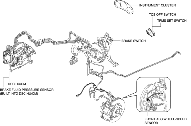
Structural View
Vehicle front side
Warning light and indicator light
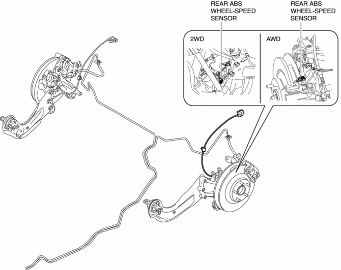
Vehicle rear side
System Wiring Diagram
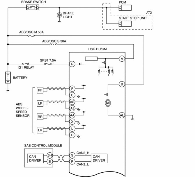

Construction
-
The DSC system consists of the following parts. While each part has a regular function in other systems, only the function during DSC control is listed.
|
Part name |
Function |
|
DSC HU/CM |
|
|
PCM |
|
|
TCM (ATX) |
|
|
EPS CM |
|
|
SAS control module |
|
|
Brake system warning light |
|
|
ABS warning light |
|
|
TCS/DSC indicator light |
|
|
TCS OFF switch |
|
|
TCS OFF indicator light |
|
|
Tire pressure monitoring system set switch |
|
|
Tire pressure monitoring system warning light |
|
|
ABS wheel-speed sensor |
|
|
Brake fluid pressure sensor (Built into DSC HU/CM) |
|
 DSC Related Parts Sensor Initialization Procedure
WARNING:
If the initialization procedure is not completed, the DSC will not operate
properly and it might cause an unexpected accident. Therefore, after replacing
or removing the DSC HU/ ...
 Ebd Control
Outline
EBD control uses the ABS system to control brake fluid pressure distribution
to the rear wheels so that they do not lock-up prior to the front wheels during
braking, thereby preve ...
Other materials:
Refrigerant Pressure Sensor [Manual Air Conditioner]
Purpose
The refrigerant pressure sensor detects the refrigerant pressure in the refrigerant
cycle.
Function
The refrigerant pressure sensor converts the detected refrigerant pressure
to an electric signal and sends it to the PCM.
Construction
The refriger ...
Rear ABS Wheel Speed Sensor Inspection [2 Wd]
Installation Visual Inspection
1. Inspect the following items:
If there is any malfunction, replace the applicable part.
a. Excessive play of the ABS wheel-speed sensor
b. Deformation of the ABS wheel-speed sensor
Clearance Inspection
1. Remove the ABS wheel-speed sensor.
2. M ...
Front Side Frame Removal [Panel Replacement]
Symbol Mark
Removal Procedure
1. Drill the 15 locations indicated by (A) shown in the figure.
2. Drill the 4 locations indicated by (B) shown in the figure.
NOTE:
When drilling the 4 locations indicated by (B) shown in the figure, do not
drill a hole all the way through or there ...
