Mazda CX-5 Service & Repair Manual: Front Seat
Purpose, Function
-
The front seats are structured to reduce impact force applied to the head of the occupant in a vehicle collision.
-
8WAY or 6WAY power seats have been adopted on the driver's seat. (with power seat system).
-
A seat warmer system has been adopted on the front seat backs and front seat cushion. (With seat warmer system).
Construction
-
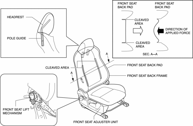
The front seats reduce impact force applied to the head of the occupant in a vehicle collision by improving the rigidity of the pole guides and setting the headrest so that it tilts to the vehicle front.
-
The front seat adjuster unit has improved rigidity by locating the front seat lift mechanism to the area around the connection part on both sides of the front seat back and the front seat cushion, and the backward lean of the front seat back when the occupant's body is pushed backward in a vehicle collision is controlled.
-
If the occupant’s body is pushed backward in a vehicle collision, the front seat back pad separates from the cleaved area and only the center part of the pad is pressed in rearward.

-
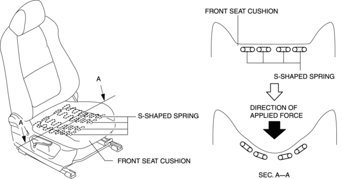
The front seat cushion is built into the S-shaped springs to absorb the impact when the occupant's body is pushed backward.

Operation
Operation (deployment) during a collision
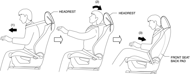
1. During a collision, the occupant moves to the vehicle front, is restrained, and the head and body of the occupant are returned back to the front seat side in reaction to that.
2. When the head and body of the occupant are returned back, the front seat absorbs the return of the head by the headrest and pole guides to reduce impact force applied to the head of the occupant.
3. When the body of the occupant is returned back to the front seat back after absorbing the return of the head by the head restraint and pole guides, the front seat back pad separates from the cleaved area and only the center part of the pad is pressed in rearward.

Fail-safe
-
Function not equipped.
 Seats
Seats
...
 Front Seat Adjuster Unit Removal/Installation
WARNING:
Handling a side air bag improperly can accidentally operate (deploy) the
air bag, which may seriously injure you. Read the service warnings/cautions
in the Workshop Manual befor ...
Other materials:
Air Intake Control [Full Auto Air Conditioner]
Purpose
The air intake control switches the air intake port (FRESH/REC) according
to the vehicle environment.
Function
The air intake control drives the air intake actuator and switches the air
intake door position according to the operations of the REC, FRESH and defroster ...
Seat Belt
Fastening the Seat Belt
Position the lap belt as low as possible, not on the abdominal area, then adjust
the shoulder belt so that it fits snugly against your body.
Unfastening the Seat Belt
Depress the button on the seat belt buckle.
If the belt does not fully retract, pull it out and che ...
Shroud Side Member Installation [Panel Replacement]
Symbol Mark
Installation Procedure
1. When installing new parts, measure and adjust the body as necessary to conform
with standard dimensions.
2. Drill holes for the plug welding before installing the new parts.
3. After temporarily installing new parts, make sure the related parts fit p ...
