
Mazda CX-5 Service & Repair Manual: Electric Variable Valve Timing Motor/Driver Inspection
WARNING:
-
A hot engine can cause severe burns. Turn off the engine and wait until it is cool before servicing.
CAUTION:
-
Do not disassemble the electric variable valve timing motor/driver because it is a precision unit.
-
Do not apply excessive force when rotating the electric variable valve timing motor joint. If it is rotated with excessive force, the electric variable valve timing motor could be damaged.
1. Disconnect the negative battery cable..
2. Remove the plug hole plate..
3. Remove the electric variable valve timing motor/driver..
4. Rotate the electric variable valve timing motor joint to the left and right by your fingers and verify that it rotates smoothly in 15°
increments.
NOTE:
-
Rotate the joint area smoothly using only the tips of your fingers.
-
The electric variable valve timing motor joint moves in 15°
increments, and if the joint is moved 24
times, it rotates one full rotation.
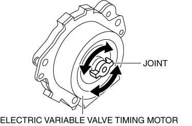
-
If it does not rotate smoothly, replace the electric variable valve timing motor/driver.(See ELECTRIC VARIABLE VALVE TIMING MOTOR/DRIVER REMOVAL/INSTALLATION [SKYACTIV-G 2.0].)
5. Install in the reverse order of removal.
 Electric Variable Valve Timing Actuator, Hydraulic Variable Valve Timing Actuator
Removal/Installation
Electric Variable Valve Timing Actuator, Hydraulic Variable Valve Timing Actuator
Removal/Installation
WARNING:
A hot engine can cause severe burns. Turn off the engine and wait until it
is cool before servicing.
CAUTION:
Do not disassemble the electric variable valve timing ac ...
 Electric Variable Valve Timing Motor/Driver Removal/Installation
WARNING:
A hot engine can cause severe burns. Turn off the engine and wait until it
is cool before servicing.
CAUTION:
Applying excessive force (force of 100 N {10.2 kgf, 22.5 ...
Other materials:
Upper Cowl Side Reinforcement Installation [Panel Replacement]
Symbol Mark
Installation Procedure
1. When installing new parts, measure and adjust the body as necessary to conform
with standard dimensions.
2. Drill holes for the plug welding before installing the new parts.
3. After temporarily installing new parts, make sure the related parts fit p ...
Oil Pressure Switch Inspection
1. Switch the ignition ON (engine off) and verify that the oil pressure warning
light is illuminated.
2. Start the engine and verify that the oil pressure warning light turns off.
If the oil pressure warning light is not illuminated or remains illuminated,
inspect the wiring harness ...
Key Warning Light (Red)/Key Indicator Light (Green)
Purpose
KEY warning light (red)
The KEY warning indicator light (red) notifies the user that the engine cannot
be started, the remote transmitter is outside of the vehicle, or that there
is a malfunction in the system.
KEY indicator light (green)
The KEY indicator light (g ...
