Mazda CX-5 Service & Repair Manual: On/Off Solenoid Removal/Installation [Fw6 A EL, Fw6 Ax EL]
WARNING:
-
A hot transaxle and ATF can cause severe burns. Turn off the engine and wait until they are cool.
-
Always wear protective eye wear when using the air compressor. If the air compressor is used, any particles of dirt or soiling could spatter and get into the eyes.
1. Disconnect the negative battery cable..
2. Remove the front under cover No.2..
3. Clean the transaxle exterior throughout with a steam cleaner or cleaning solvents.
4. Drain the ATF..
5. Remove the oil pan.
CAUTION:
-
To avoid damaging the control valve body, if there is a large amount of foreign material at the bottom of the oil pan when the oil pan is removed, replace the oil strainer with a new one.
-
If there is not a large amount of foreign material at the bottom of the oil pan, the oil strainer does not have to be replaced.
6. Disconnect the ON/OFF solenoid connector.
NOTE:
-
Disconnect the ON/OFF solenoid connector by pressing the connector tab with your fingers.
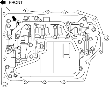
7. Remove the ON/OFF solenoid.
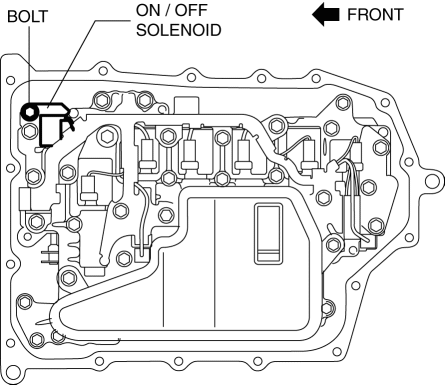
8. Install the ON/OFF solenoid.
-
Tightening torque
-
9—10 N·m {92—101 kgf·cm, 80—88 in·lbf}
9. Connect the ON/OFF solenoid connector.
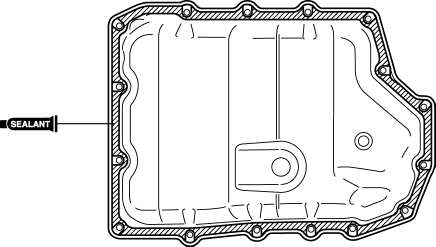
10. Apply a light coat of silicon sealant (TB1217E) to the contact surfaces of the oil pan and transaxle case.
CAUTION:
-
Clean any remaining silicone sealant on the contact surface of the transaxle case and oil pan, and degrease the sealant area. Otherwise, oil could leak.
11. Install the oil pan with new bolts before the applied sealant starts to harden.
-
Tightening torque
-
8—10 N·m {82—101 kgf·cm, 71—88 in·lbf}
12. Install the front under cover No.2..
13. Add the ATF..
14. Connect the negative battery cable..
15. Perform the “Mechanical System Test”..
 Oil Seal (Control Valve Body) Replacement [Fw6 A EL, Fw6 Ax EL]
1. Disconnect the negative battery cable..
2. Remove the air cleaner component..
3. Disconnect the control valve body connector.
CAUTION:
Make sure that your hand does not touch the ...
 On/Off Solenoid [Fw6 A EL, Fw6 Ax EL]
Purpose/Function
The on/off solenoid performs switching of the shift valve in the control
valve body according to the vehicle conditions.
Construction
The on/off solenoid is ins ...
Other materials:
Rear Window Glass Removal
1. Disconnect the negative battery cable..
2. Remove the following parts:
a. Liftgate upper trim.
b. Liftgate side trim.
c. Liftgate recess.
d. Liftgate lower trim.
e. Rear spoiler.
f. Rear wiper arm and blade.
g. Rear wiper motor.
3. Using a screwdriver wrapped in protective tape, ...
Meters and Gauges
1 Speedometer
2 Odometer, Trip Meter and Trip Meter Selector
3 Tachometer
4 Fuel Gauge
5 Dashboard Illumination
6 Outside Temperature Display
7 Trip Computer and INFO Switch
Speedometer
The speedometer indicates the speed of the vehicle.
Odometer, Trip Meter and Trip Meter Selector
...
Power Brake Unit Removal/Installation
CAUTION:
Once the brake switch clearance has automatically been adjusted, it cannot
be adjusted again. Therefore, replace the switch with a new one when replacing
the power brake unit or performing any procedure that changes the pedal stroke.
1. Remove the battery and battery tra ...
