
Mazda CX-5 Service & Repair Manual: Crankshaft Position (CKP) Sensor Inspection
Visual Inspection
CAUTION:
-
When foreign material such as an iron chip is on the CKP sensor, it can cause abnormal output from the sensor because of flux turbulence and adversely affect the engine control. Be sure there is no foreign material on the CKP sensor when replacing.
-
Do not assemble the CKP sensor or change the installation position using any method other than the following. Otherwise, it could negatively affect engine controls, such as the ignition timing and fuel injection.
1. Remove the CKP sensor..
2. Verify that there are no metal shavings on the sensor.
-
If there is a malfunction, remove any metal shavings that are adhering.
Voltage Inspection
CAUTION:
-
When foreign material such as an iron chip is on the CKP sensor, it can cause abnormal output from the sensor because of flux turbulence and adversely affect the engine control. Be sure there is no foreign material on the CKP sensor when replacing.
-
Do not assemble the CKP sensor or change the installation position using any method other than the following. Otherwise, it could negatively affect engine controls, such as the ignition timing and fuel injection.
-
If the wiring harnesses or waterproof connectors are damaged, water penetrating the connector will cause a sensor malfunction. To prevent this, be careful not to damage wiring harnesses or waterproof connectors.
1. Idle the engine.
2. Measure the CKP sensor output voltage using the oscilloscope.
-
If not as specified, replace the CKP sensor..
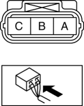
|
Terminal |
Voltage (V) |
Condition |
|
A |
Approx. 5.0 |
Under any condition |
|
B |
Below 1.0 |
Under any condition |
|
C |
Above 4.5 |
High output* |
|
Below 0.8 |
Low output* |
* Output voltage varies with crankshaft rotation.
 Camshaft Position (CMP) Sensor
Purpose/Function
Detects the camshaft speed as basic information for mainly determining the
fuel injection timing and ignition timing.
Detects the camshaft speed and inputs it to the ...
 Crankshaft Position (CKP) Sensor Removal/Installation
CAUTION:
When foreign material such as an iron chip is on the CKP sensor, it can cause
abnormal output from the sensor because of flux turbulence and adversely affect
the engine control. ...
Other materials:
Awd Control Module Removal/Installation
CAUTION:
When performing configuration, it is necessary to read the coupling component
calibration data from the AWD control module before replacing it. Connect the
M-MDS to the vehicle and perform vehicle identification before removing the
AWD control module. The coupling component ...
Rear Door Trim Removal/Installation
1. Insert a tape-wrapped flathead screwdriver in the position indicated by the
arrow (1) in the figure and remove the inner handle cover while detach tabs A, pin
B.
2. Remove the screw C.
3. Remove the cover D, then remove the screw E.
4. Take the shaded area shown in the figur ...
Shift Pressure Control (Line Pressure Control) [Fw6 A EL, Fw6 Ax EL]
Outline
The TCM drives the pressure control solenoid and adjusts the pressure based
on the accelerator pedal depression amount, vehicle speed, ATF temperature,
and gear shift signal. As a result, line pressure is controlled finely and with
high accuracy according to the engine load c ...
