Mazda CX-5 Service & Repair Manual: Clock Spring Removal/Installation [Standard Deployment Control System]
CAUTION:
-
If the disc on the combination switch is deformed or has foreign material adhering to it, performance of the steering angle sensor may be reduced, causing abnormal operation. When handling the clock spring, be careful not to deform the disc and make sure there is no foreign material on it.
1. Switch the ignition to off.
2. Disconnect the negative battery cable and wait for 1 min or more
..
3. Remove the driver?side air bag module..
4. Remove the steering wheel..
5. Remove the column cover..
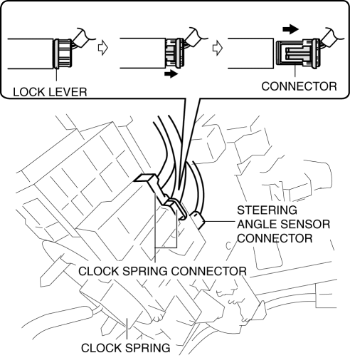
6. Disconnect the clock spring connector.

7. Disconnect the steering angle sensor connector. (with steering angle sensor)
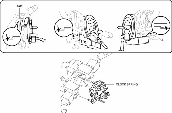
8. Remove the tab direction of the arrow shown in the figure and remove the clock spring.

9. Install in the reverse order of removal..
10. Verify that the air bag system warning light illuminates for approx. 6 s
and goes out.
-
If the air bag system warning light does not operate in the manner described above, there are malfunctions in the system. Inspect the system using the on-board diagnostic..
Clock Spring Installation Note
CAUTION:
-
If the clock spring is not adjusted, the spring wire in the clock spring will break due to overtension when the steering wheel is turned. Always adjust the clock spring after installing it.
-
Adjust the clock spring after installing it..
 Clock Spring Inspection [Two Step Deployment Control System]
1. Disconnect the negative battery cable and wait for 1 min or more..
2. Remove the driver?side air bag module..
3. Remove the steering wheel..
4. Remove the column cover..
5. Remove the cloc ...
 Control System Personalization Features Setting Procedure
1. Connect the M-MDS to DLC-2.
2. After the vehicle is identified, select the following items from the initial
screen of the M-MDS.
Select the “Module Programming”.
Select “P ...
Other materials:
Rear Seat Belt Removal/Installation
CAUTION:
The ELR (emergency locking retractor) has a spring that will unwind if the
retractor cover is removed. The spring cannot be rewound by hand. If this occurs,
the ELR will not work properly. Therefore, do not disassemble the retractor.
1. Remove the following parts:
a. T ...
Audio Set (Type A)
1 Power/Volume/Sound Controls
2 Operating the Radio
3 Operating the Compact Disc (CD) Player
4 How to use auxiliary jack/USB port
5 Error Indications
Power/Volume/Sound Controls
Power ON/OFF
Switch the ignition to ACC or ON. Press the power/volume dial to turn the audio
system on. Pre ...
Tcs Control
Outline
The TCS control actuates torque reduction through engine control, as well
as using brake control to control traction.
NOTE:
Engine control: Engine output is lowered by fuel cut and ignition timing
control to reduce the traction, preventing driving wheel slip.
...
