Mazda CX-5 Service & Repair Manual: C Pillar Trim Removal/Installation
1. Disconnect the negative battery cable..
2. Remove the following parts:
a. Trunk board.
b. Trunk end trim.
c. Rear scuff plate.
d. Trunk side trim.
e. D-pillar trim.
3. Partially peel back the seaming welt.
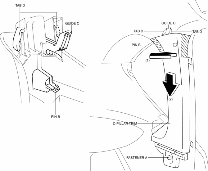
4. Remove the fastener A.

5. Take the shaded area shown in the figure, and pull the C-pillar trim in the direction of the arrow (1) while detaching the pin B.
6. Remove the C-pillar trim in the direction of the arrow (2) shown in the figure while detaching guide C, tabs D.
CAUTION:
-
If the C-pillar trim is pulled in the direction of the arrow (1) forcefully, guide C may be damaged. Carefully pull the C-pillar trim so as not to damage guide C.
7. Install in the reverse order of removal.
 B Pillar Upper Trim Removal/Installation
1. Remove the following parts:
a. Front scuff plate.
b. Rear scuff plate.
c. B-pillar lower trim.
d. Adjuster anchor cover.
e. Upper anchor installation bolts on the front seat belt.
2. Pa ...
 Center Panel Removal/Installation
1. Disconnect the negative battery cable..
2. Remove the decoration panel.
3. Take the shaded area shown in the figure, and pull the center panel in the
direction of the arrow in the order of (1 ...
Other materials:
Air Bag Module And Pre Tensioner Seat Belt Deployment Procedures [Two Step Deployment
Control System]
WARNING:
A live (undeployed) air bag module, pre-tensioner seat belt or lap pre-tensioner
seat belt may accidentally operate (deploy) when it is disposed of and cause
serious injury. Do not dispose of a live (undeployed) air bag module, pre-tensioner
seat belt or lap pre-tensioner s ...
Sunvisors
When you need a sunvisor, lower it for use in front or swing it to the side.
Side Extension Sunvisors
The visor extender extends the sunvisor's range of sun shading.
To use, pull it out.
CAUTION
When moving the sunvisor, retract the visor extender to its original position.
Otherwise, ...
Rear Door Speaker Inspection
1. Disconnect the negative battery cable..
2. Remove the rear door trim..
3. Disconnect the rear door speaker connector..
4. Verify that the resistance between the rear door speaker terminals is as indicated
in the table.
If not as indicated in the table, replace the rear door sp ...
