Mazda CX-5 Service & Repair Manual: Brake Pedal
Purpose/Function
-
An intrusion-minimizing brake pedal has been adopted to the brake pedal to provide for a measure of safety in the event of an accident.
-
The intrusion-minimizing brake pedal mechanism reduces impact to the lower extremities of the driver by minimizing the amount of rearward brake pedal thrust in a frontal collision.
Construction
-
The intrusion minimizing brake pedal mechanism is structured on the brake pedal and consists of the following parts.
-
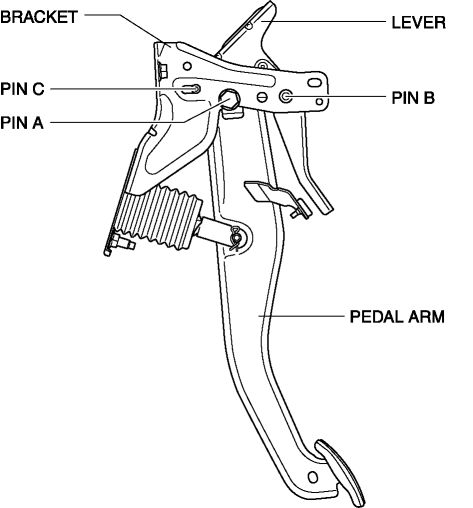
Pedal arm
-
Lever
-
Pin A
-
Pin B
-
Pin C
-
Bracket
Operation
During normal braking
-
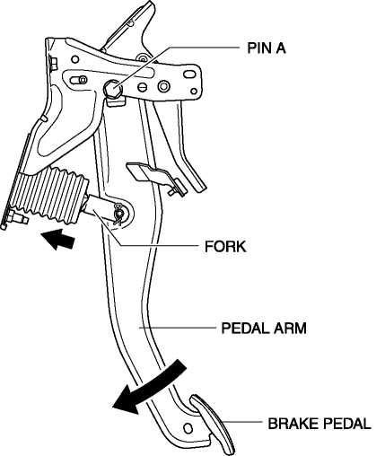
When the brake pedal is depressed, the pedal arm rotates at the pin A fulcrum point, and the pedal depression force is transmitted to the fork of the power brake unit.
-
This pedal depression force pushes in the fork to operate the brakes.
Intrusion-minimizing operation
-
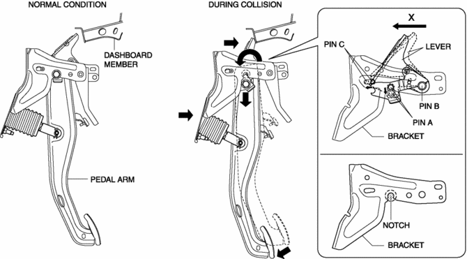
In a frontal collision, the brake pedal is forced rearward by the movement of the dashboard.
-
In response to this, force in the direction of X is applied to the brake pedal lever because the dashboard member and brake pedal lever interfere.
-
With the addition of force in the direction of X, pin C releases from the lever, and the lever rotates around the pin B fulcrum point.
-
When the lever rotates, it obstructs pin A at the fulcrum point of the pedal arm.
-
If the pedal rotates further, pin A separates from the bracket (notch), and the pedal is freed.
-
By freeing the pedal arm, the force applied to the lower extremities is reduced.
 Brake Hose (Rear) Removal/Installation
1. Remove in the order indicated in the table.
2. Install in the reverse order of removal.
3. After installation, add brake fluid, bleed the air, and inspect for fluid
leakage..
...
 Brake Pedal Inspection
Pedal Height Inspection
1. Measure the distance from the center of the upper surface of the pedal pad
to the insulator and verify that it is as specified.
If not within the specificatio ...
Other materials:
Front Under Cover No.1 Removal/Installation
1. Remove bolts A.
2. Remove screws B.
3. Remove fasteners C.
4. Remove the front under cover No.1 in the direction of the arrow in the order
of (1), (2) shown in the figure while detaching the guide D.
5. Install in the reverse order of removal. ...
Front Body Straight Line Dimensions (2) [Dimensions]
Point symbol
Designation
Hole diameter or bolt or nut size mm {in}
A
Roof seamless location
-
B
Cabin side outer frame (front pillar outer) projection location
-
...
Steering Gear And Linkage Removal/Installation
CAUTION:
Performing the following procedures without first removing the ABS wheel-speed
sensor may possibly cause an open circuit in the wiring harness if it is pulled
by mistake. Before performing the following procedures, disconnect the ABS wheel-speed
sensor (axle side) and fix t ...
