Mazda CX-5 Service & Repair Manual: Brake Pedal Inspection
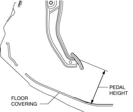
Pedal Height Inspection
1. Measure the distance from the center of the upper surface of the pedal pad to the insulator and verify that it is as specified.

-
If not within the specification, inspect the following items and repair or replace the applicable part if there is any malfunction.
-
Power brake unit installation condition
-
Deformation of or damage to the power brake unit fork
-
Brake pedal installation condition
-
Clevis pin wear
-
If there is no malfunction in the above items, replace the brake pedal.
-
Brake pedal height (reference value)
-
136 mm {5.35 in}
Pedal Play Inspection
1. Pump the pedal several times to release the vacuum in the power brake unit.
2. Gently depress the pedal by hand and measure the pedal play.
-
If not within the specification, inspect the wear of the clevis pin. Replace it if there is any malfunction.
-
Brake pedal play
-
3—5 mm {0.12—0.19 in}
NOTE:
-
If there is no malfunction in the clevis pin, there is a possibility that the power brake unit has some malfunction. Verify that there are no malfunctions, and replace it if necessary.
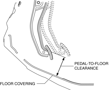
Pedal-to-floor Clearance Inspection
1. Start the engine and depress the brake pedal with a force of 147 N {15.0 kgf, 33.0 lbf}
.
2. Measure the distance from the center of the upper surface of the pedal pad to the floor covering and verify that it is as specified.

-
If it is less than the specification, inspect for air in the brake line.
-
Brake pedal-to-floor clearance (Brake pedal when depressed at 147 N {15.0
kgf, 33.0 lbf})
-
95 mm {3.7 in} or more
 Brake Pedal
Purpose/Function
An intrusion-minimizing brake pedal has been adopted to the brake pedal to
provide for a measure of safety in the event of an accident.
The intrusion-minimizing brak ...
 Brake Pedal Removal/Installation
CAUTION:
The clearance between the brake switch and the brake pedal is automatically
adjusted to the correct amount when the brake switch is inserted into the installation
hole on the br ...
Other materials:
Glass Antenna
Purpose, Function
The RDS (Radio Data System) converts radio broadcast waves to electric signals
and sends the signals to the audio unit.
Construction
An antenna with excellent noise resistance has been adopted to the rear window
glass.
Fail-safe
Function n ...
Suspension
49 T034 1A0
Coil spring compressor set
49 T028 3A0
Ball joint puller set
49 G033 102
Handle
49 U034 204
Dust boot installer
49 FT01 389
Pr ...
Electronic Spark Advance Control [Skyactiv G 2.0]
Outline
Controls ignition to optimum timing according to engine operation conditions.
Serviceability has been improved by eliminating the necessity of ignition
timing adjustment.
The PCM determines the engine operation conditions based on input signals
from each sensor a ...
