
Mazda CX-5 Service & Repair Manual: Audio System
NOTE:
-
“iPod” is a registered trademark of Apple Inc. in the United States and other countries.
Outline
-
An audio unit compatible with AM/FM tuner and MP3/WMA (Windows Media Audio)/AAC (Advanced Audio Coding) has been adopted.
-
There are two types of audio units, one with color LCD and one without it.
-
An audio unit compatible with HD radio has been adopted.
-
ALC (auto level control) function has been adopted. (With Bose ®)
-
A road noise correction system (AudioPilot®2) has been adopted. (With Bose ®)
-
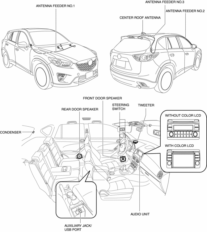
Three types of speakers have been provided as follows:
-
Front door speaker
-
Rear door speaker
-
Front door speaker
-
Rear door speaker
-
Tweeter
-
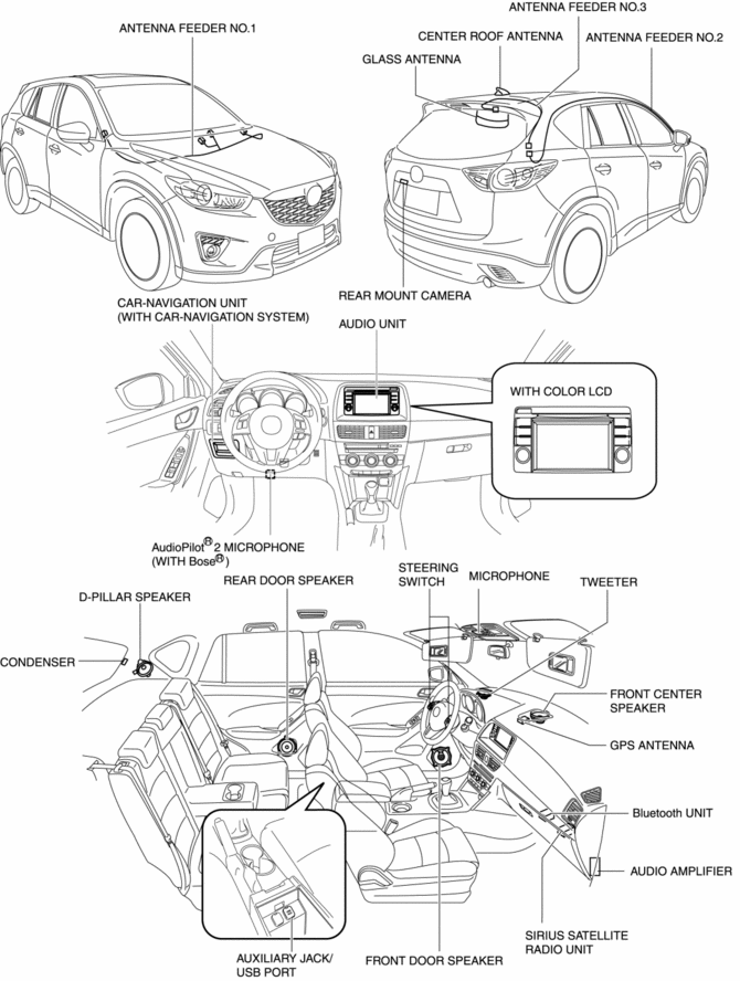
Front door speaker
-
Rear door speaker
-
Front center speaker
-
D-pillar speaker
-
Tweeter
-
The steering switch enables the driver to operate a part of the audio system functions and change the trip computer display without changing the driving posture.
-
A rear mount camera has been adopted which monitors the conditions at the rear of the vehicle when reversing, and outputs a video signal to the audio unit. (With color LCD)
-
A SIRIUS satellite radio antenna which can receive SIRIUS satellite radio has been adopted. (with SIRIUS satellite radio unit)
-
An auxiliary jack/USB port has been adopted which can connect to commercially-available portable audio/USB devices/iPod, and output sound from the speakers via the audio unit.
-
A condenser has been adopted to the D-pillar for noise reduction.
-
4 speaker type (without Bose ®)
-
6 speaker type (without Bose ®)
-
9 speaker type (with Bose ®)
Function
-
The audio system has the following functions:
ALC (auto level control) function (without Bose ®)
-
Compensates for the passengers' sense of a lack of audio volume which occurs as a result of external noise while driving.
Road noise correction system (AudioPilot®2) (with Bose ®)
-
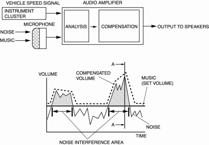
The volume of the music constituent covered by noise is corrected by the audio amplifier based on the cabin noise measured by the two AudioPilot®2 microphones and the vehicle speed signal sent from the instrument cluster.
Operation sound function
-
When the audio panel, climate control unit, steering switch, and clock unit buttons and switches are operated, an operation sound is output.
On-board diagnostic function
-
Performs on-board diagnosis to detect the location of a malfunction.
-
For details on the on-board diagnostic function, refer to the On-board Diagnostic System [Audio System].
Diagnostic Assist Function
-
Can verify specifications, connection status and operation status of audio system related parts.
-
For details on the diagnostic assist function, refer to the On-board Diagnostic System [Audio System].
Structural view
Without Bose®
With Bose®
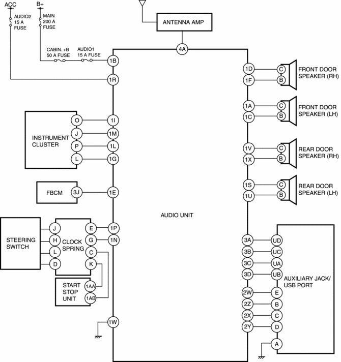
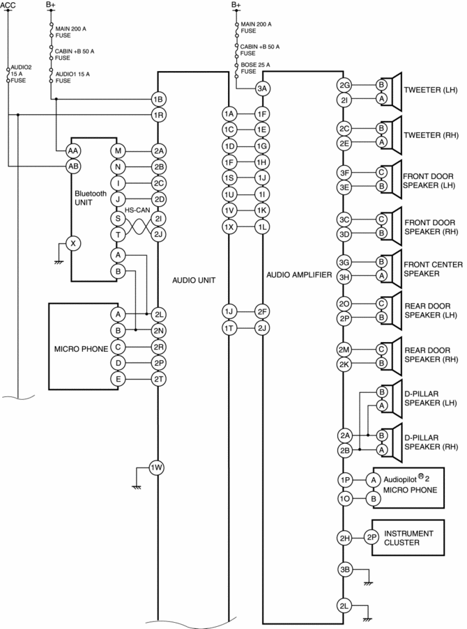
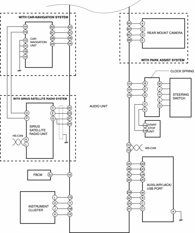
Block diagram
Without color LCD
With color LCD (Without Bose ®)
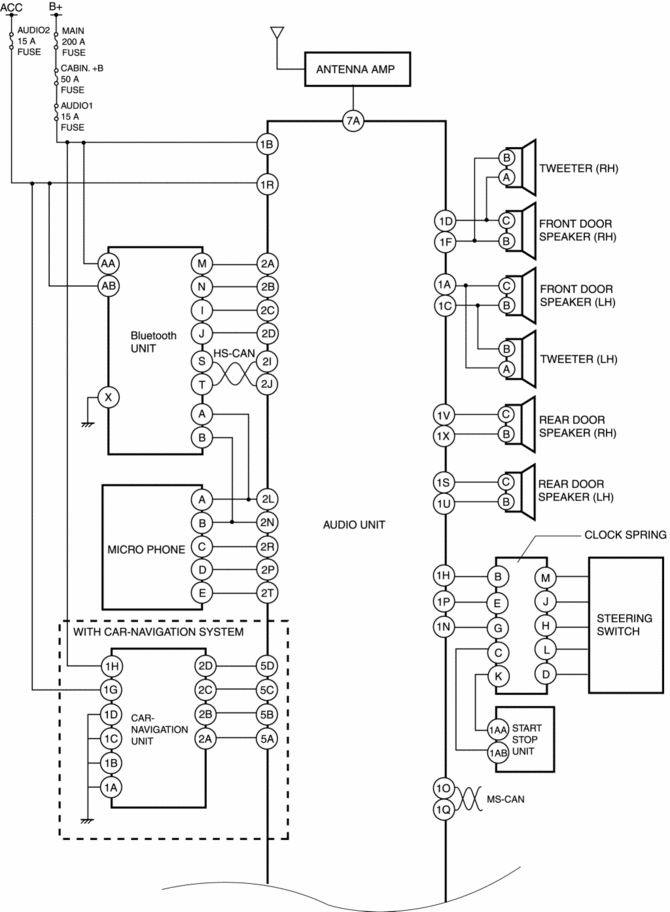
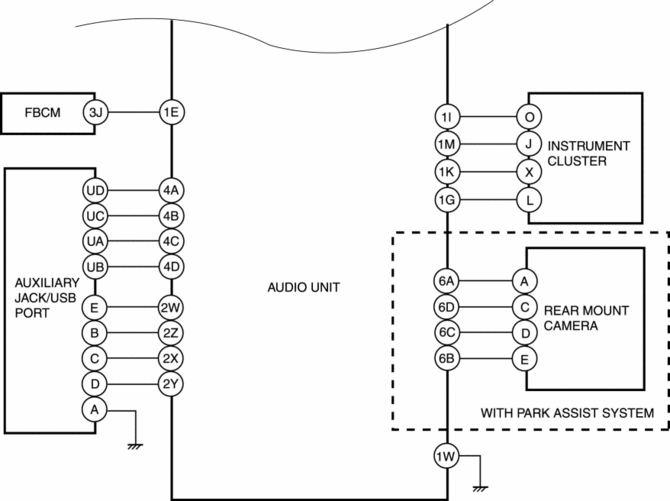
WITH COLOR LCD (With Bose ®)
Operation
CD operation
-
Without Bose®
-
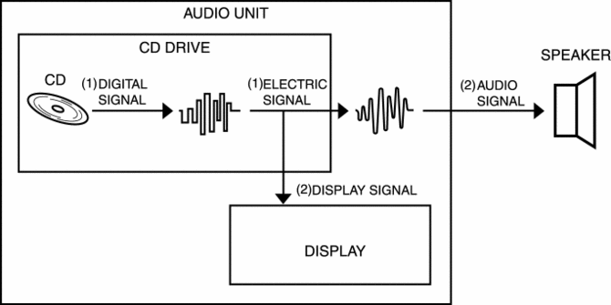
When a CD is inserted into the audio unit, laser light is emitted to the CD by the CD drive in the audio unit. The reflected light is detected by the light sensor and the data recorded in the CD is converted from a digital signal to an electric signal.
-
The audio unit converts the electric signal to an audio signal and video signal using the electrical circuit in the audio unit. The audio signal is sent to the speakers and the video signal is sent to the audio display.
-
The speakers generate audio based on the audio signal sent from the audio unit. The audio unit displays CD information based on the video signal.
-
With Bose®
-
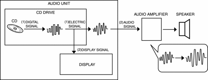
When a CD is inserted into the audio unit, laser light is emitted to the CD by the CD drive in the audio unit. The reflected light is detected by the light sensor and the data recorded in the CD is converted from a digital signal to an electric signal.
-
The audio unit converts the electric signal to an audio signal and video signal using the electrical circuit in the audio unit. The audio signal is sent to the speakers and the video signal is sent to the audio display.
-
The audio amplifier amplifies the audio signal sent from the audio unit and sends it to the speakers.
-
The speakers generate audio based on the audio signal sent from the audio unit. The audio display displays CD information based on the video signal.
Radio operation
-
Without Bose®
-
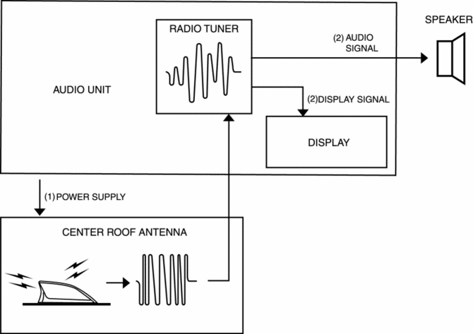
When the ignition is switched to ACC or ON (engine off or on), the audio unit supplies power to the amplifier in the center roof antenna.
-
The audio unit detects the radio broadcast selected by the user using the radio tuner in the audio unit based on the electrical signal sent from the center roof antenna. The audio signal from the detected radio broadcast is then sent to the speakers. In addition, the video signal of the detected radio broadcast is sent to the display of the audio unit.
-
The speakers generate audio based on the audio signal sent from the audio unit. The audio display displays radio information based on the video signal.
-
With Bose®
-
When the ignition is switched to ACC or ON (engine off or on), the audio unit supplies power to the amplifier in the center roof antenna.
-
The audio unit detects the radio broadcast selected by the user using the radio tuner in the audio unit based on the electrical signal sent from the center roof antenna. The audio signal from the detected radio broadcast is then sent to the audio amplifier. In addition, the video signal of the detected radio broadcast is sent to the display of the audio unit.
-
The audio amplifier amplifies the audio signal sent from the audio unit and sends it to the speakers.
-
The speakers produce audio based on the audio signal sent from the audio unit. The audio display displays radio information based on the video signal.

-
ALC (auto level control) operation (without Bose ®)
-
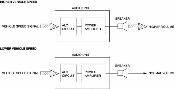
The audio unit automatically changes the volume and audio quality based on the vehicle speed signal sent from the instrument cluster.
-
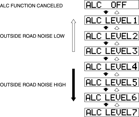
The ALC function is divided into 7 levels. When the level is in the high range, the volume correction range and correction amount is large. The maximum correction amount is 14dB. The ALC function can be stopped by selecting ALC OFF.
|
Vehicle speed (km/h {mph}) |
ALC LEVEL 1 (dB) |
ALC LEVEL 2 (dB) |
ALC LEVEL 3 (dB) |
ALC LEVEL 4 (dB) |
ALC LEVEL 5 (dB) |
ALC LEVEL 6 (dB) |
ALC LEVEL 7 (dB) |
|
0—15 {0—9.3} |
0 |
0 |
0 |
0 |
0 |
0 |
0 |
|
20 {12} |
0 |
0 |
0 |
0 |
0 |
0 |
1 |
|
25 {16} |
0 |
0 |
1 |
1 |
1 |
1 |
1 |
|
30 {19} |
0 |
1 |
1 |
1 |
1 |
1 |
2 |
|
35 {22} |
1 |
1 |
1 |
1 |
2 |
2 |
2 |
|
40 {25} |
1 |
1 |
1 |
2 |
2 |
2 |
3 |
|
45 {28} |
1 |
1 |
2 |
2 |
2 |
3 |
3 |
|
50 {31} |
1 |
1 |
2 |
2 |
3 |
3 |
4 |
|
55 {34} |
1 |
2 |
2 |
3 |
3 |
4 |
4 |
|
60 {37} |
1 |
2 |
2 |
3 |
4 |
4 |
5 |
|
65 {40} |
1 |
2 |
3 |
3 |
4 |
5 |
5 |
|
70 {43} |
1 |
2 |
3 |
4 |
4 |
5 |
6 |
|
75 {47} |
2 |
2 |
3 |
4 |
5 |
6 |
7 |
|
80 {50} |
2 |
3 |
3 |
4 |
5 |
6 |
7 |
|
85 {53} |
2 |
3 |
4 |
5 |
6 |
7 |
8 |
|
90 {56} |
2 |
3 |
4 |
5 |
6 |
7 |
8 |
|
95 {59} |
2 |
3 |
4 |
5 |
7 |
8 |
9 |
|
100 {62.1} |
2 |
3 |
5 |
6 |
7 |
8 |
9 |
|
105 {65.2} |
2 |
4 |
5 |
6 |
7 |
9 |
10 |
|
110 {68.4} |
2 |
4 |
5 |
6 |
8 |
9 |
10 |
|
115 {71.5} |
3 |
4 |
5 |
7 |
8 |
10 |
11 |
|
120 {74.6} |
3 |
4 |
6 |
7 |
9 |
10 |
11 |
|
125 {77.7} |
3 |
4 |
6 |
7 |
9 |
10 |
12 |
|
130 {80.8} |
3 |
5 |
6 |
8 |
9 |
11 |
13 |
|
135 {83.9} |
3 |
5 |
6 |
8 |
10 |
11 |
13 |
|
140 {87} |
3 |
5 |
7 |
8 |
10 |
12 |
14 |
|
145 {90.1} |
3 |
5 |
7 |
9 |
11 |
12 |
14 |
|
150 {93.2} |
3 |
5 |
7 |
9 |
11 |
13 |
14 |
|
155 {96.3} |
4 |
6 |
7 |
9 |
11 |
13 |
14 |
|
160 {99.4} |
4 |
6 |
8 |
10 |
12 |
14 |
14 |
|
165 {103} |
4 |
6 |
8 |
10 |
12 |
14 |
14 |
|
170 {106} |
4 |
6 |
8 |
10 |
13 |
14 |
14 |
|
175 {109} |
4 |
6 |
9 |
11 |
13 |
14 |
14 |
|
180 {112} |
4 |
7 |
9 |
11 |
13 |
14 |
14 |
|
185 {115} |
4 |
7 |
9 |
11 |
14 |
14 |
14 |
|
190 {118} |
4 |
7 |
9 |
12 |
14 |
14 |
14 |
|
195 {121} |
5 |
7 |
10 |
12 |
14 |
14 |
14 |
|
200 {124} |
5 |
7 |
10 |
12 |
14 |
14 |
14 |
|
205 {127} |
5 |
7 |
10 |
13 |
14 |
14 |
14 |
|
210 {130} |
5 |
8 |
10 |
13 |
14 |
14 |
14 |
|
215 {134} |
5 |
8 |
11 |
13 |
14 |
14 |
14 |
|
220 {137} |
5 |
8 |
11 |
14 |
14 |
14 |
14 |
|
225 {140} |
5 |
8 |
11 |
14 |
14 |
14 |
14 |
|
230 {143} |
5 |
8 |
11 |
14 |
14 |
14 |
14 |
|
235 {146} |
6 |
9 |
12 |
14 |
14 |
14 |
14 |
|
240 {149} |
6 |
9 |
12 |
14 |
14 |
14 |
14 |
|
245 {152} |
6 |
9 |
12 |
14 |
14 |
14 |
14 |
|
250 {155} |
6 |
9 |
13 |
14 |
14 |
14 |
14 |
-
Road noise correction system (AudioPilot®2) (with Bose ®)
-
The audio amplifier differentiates each of the noise and music frequencies and compares the noise and music level based on the cabin sound measured by the two microphones used with the AudioPilot®2 and by the vehicle speed signal sent from the instrument cluster. As a result, sound correction is performed if it is determined that the frequency band from the noise makes it difficult to hear the music.
-
Operation sounds
-
The audio unit outputs operation sound when it detects an operation signal from the operation of an audio panel and steering switch.
-
The operation sound is output from the front door speakers.
-
The operation sound can be set to activated/deactivated. If the operation sound is deactivated, operation sound is not output.
-
The operation sound is output as follows.
|
Signal |
Operation sound setting ON |
Operation sound setting OFF |
Sound frequency |
|
|
Audio panel switch operation signal/Steering switch operation signal |
Short-press |
|
— |
3 kHz |
|
Long-press |
|
|
3 kHz |
|



With color LCD
|
Signal |
Operation sound setting ON |
Operation sound setting OFF |
Sound frequency |
|
|
Audio panel switch operation signal/Steering switch operation signal |
Short-press |
|
— |
3 kHz |
|
Long-press |
|
— |
3 kHz |
|
|
SIRIUS seek alert |
|
— |
1.5 kHz |
|
 Audio Pilot®2 Microphone Removal/Installation
NOTE:
AudioPilot®2 is a registered trademark of Bose® Corporation.
1. Disconnect the negative battery cable..
2. Remove the following parts:
a. Driver-side front scuff plate.
b. ...
 Audio Unit (With Color LCD)
NOTE:
“iPod” is a registered trademark of Apple Inc. in the United States and other
countries.
Purpose
The audio unit controls the CD, radio, exterior input devices (AUX/US ...
Other materials:
Wheels And Tires
Outline
An adhesive-type balance weights has been adopted to the outer side of the
aluminum alloy wheels. Due to this, a stylish wheel design is realized.
In consideration of the environment, steel balance weights have been adopted
to reduce the use of lead in the vehicle.
...
Rear Seat
Split Folding
The seatbacks can be folded down to provide more space in the luggage compartment.
WARNING
Tightly secure cargo in the luggage compartment when it is transported
with the seatbacks folded down:
Driving without tightly securing cargo and luggage is dangerous as it could move
and ...
Outside the United States/Canada
Government regulations in the United States/Canada require that automobiles meet
specific emission regulations and safety standards. Therefore, vehicles built for
use in the United States/Canada may differ from those sold in other countries.
The differences may make it difficult or even impossi ...
