Mazda CX-5 Service & Repair Manual: Steering Switch Removal/Installation
WARNING:
-
Handling the driver-side air bag module improperly can accidentally operate (deploy) the air bag module, which may seriously injure you. Read the service warnings and cautions before handling the air bag module..
1. Switch the ignition OFF (LOCK).
2. Disconnect the negative battery cable and wait for 1 min or more
..
3. Remove the driver-side air bag module..
4. Remove the steering wheel..
5. Affix protective tape to the gaps between the steering wheel and cover as shown in the figure.
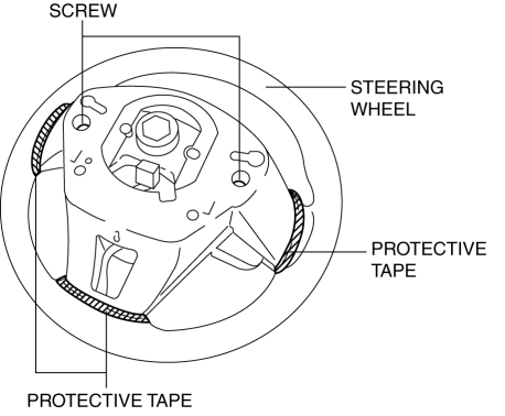
6. Remove the screws.
7. Using a tape-wrapped flathead screwdriver, press the cover tabs in the direction of the arrows shown in the figure to detach the cover tabs from the steering wheel.
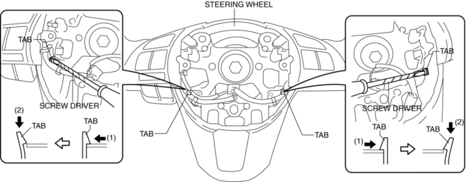
8. Insert the fastener remover into the clearance between the steering wheel and cover as shown in the figure.
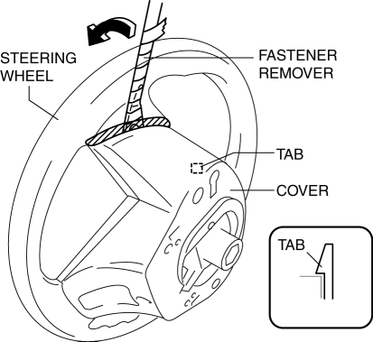
9. Move the fastener remover in the direction of the arrow shown in the figure and detach cover tab from the steering wheel.
10. Remove the cover while detaching the pins from the steering wheel.
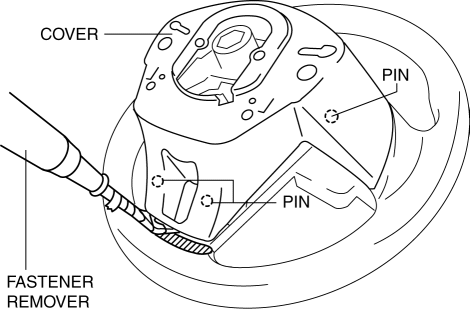
11. While pressing the clip tabs in the direction of the arrows (1) shown in the figure, press the clip in the direction of the arrow (2) to detach the clip tabs from the steering wheel.
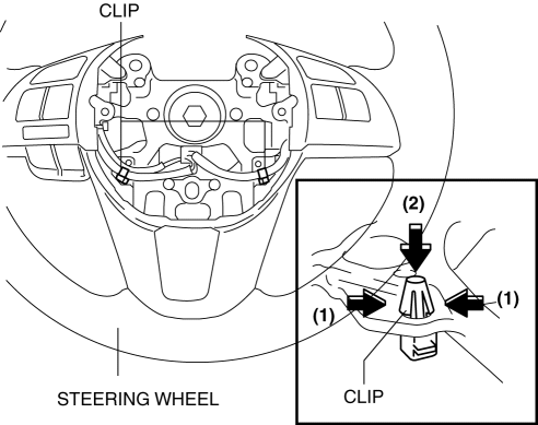
12. Detach the clip.
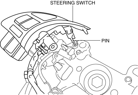
13. While pressing the tabs of the steering switch in the direction of the arrows (1) shown in the figure, press the steering switch in the direction of the arrow (2) to detach the tabs of the steering switch from the steering wheel.
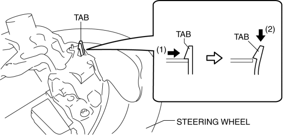
14. Insert a fastener remover into the position shown in the figure.
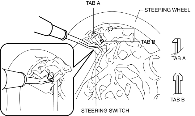
15. Move the fastener remover straight in the direction shown in the figure and remove the tabs of the steering switch from the steering wheel.
CAUTION:
-
When removing the pins of the steering switch, pull them out straight. If the fastener remover is moved at an angle, the pins could be damaged.
NOTE:
-
Because the pins of the steering switch are installed to the hard plastic area of the steering wheel, the engagement is strong.
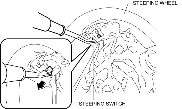
16. Remove the steering switch while detaching the pin and tabs of the steering wheel.
17. Install in the reverse order of removal.
 Steering Switch Inspection
Without Bluetooth system
WARNING:
Handling the driver-side air bag module improperly can accidentally operate
(deploy) the air bag module, which may seriously injure you. Read the service ...
 Linkage, Power
...
Other materials:
Lower Cowl Side Reinforcement Installation [Panel Replacement]
Symbol Mark
Installation Procedure
1. When installing new parts, measure and adjust the body as necessary to conform
with standard dimensions.
2. Drill holes for the plug welding before installing the new parts.
3. After temporarily installing new parts, make sure the related parts fit p ...
Front Outer Handle Removal/Installation
1. Perform the front door glass preparation..
2. Disconnect the negative battery cable..
3. Remove the following parts:
a. Inner garnish.
b. Front door trim.
c. Front door glass.
d. Front door module panel.
e. Front door key cylinder.
4. Disconnect the keyless antenna connector (With ...
Installing Child-Restraint Systems
Accident statistics reveal that a child is safer in the rear seat. The front
passenger's seat is clearly the worst choice for any child under 12, and with rear-facing
childrestraint systems it is clearly unsafe due to air bags.
NOTE
Even if your vehicle is equipped with front passenger sea ...
