Mazda CX-5 Service & Repair Manual: Spark Plug Inspection [Skyactiv G 2.0]
Specification
-
Spark plug type
-
PE01-18110, PE02-18110
Plug Gap Inspection
CAUTION:
-
To avoid possible damage to the tip, do not adjust the plug gap.
-
To prevent damaging the tip, use a wire type plug gap gauge when inspecting the plug gap.
1. Measure the spark plug gap using a wire type plug gap gauge.
-
If not within the standard specification, replace the spark plug.
-
Spark plug gap
-
Standard: 0.75—1.10 mm {0.030—0.043 in}
-
New spark plug (reference): 0.75—0.85 mm {0.030—0.033 in}
Cleaning
CAUTION:
-
Carbon may adhere to the tip of the spark plug during vehicle delivery or repeated short distance driving during the winter time. If there is any malfunction such as rough idling or start difficulty due to carbon adhesion causing plug fouling, burn off the carbon by performing no-load racing of the engine.
-
When performing the no-load racing, apply the side brake and foot brake, move the shift lever to neutral (MTX), or the selector lever to P position (ATX) to prevent an accident and serious injury.
-
To avoid possible damage to the spark plug tip, do not use a wire brush for cleaning.
NOTE:
-
To avoid possible damage to the tip, use gasoline to clean the spark plugs after removing dirt.
-
If the accelerator pedal is depressed continuously for a specified time, the engine speed may decrease to the idle speed. This is due to the PCM control operation, which prevents overheating, and it does not indicate a malfunction.
-
Do not perform no-load racing at high engine speed continuously for 10 s or more
.
1. If there is carbon adhering to the spark plug, perform no-load racing at 4,000 rpm
for 2 min
, 2 times
.
Visual Inspection
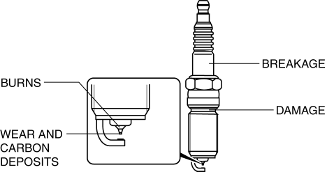
1. Inspect the following items:

-
If any of the following malfunctions are indicated, replace the spark plug.
-
Insulator breakage
-
Worn electrode
-
Damaged gasket
-
Badly burned insulator (sparking side)
Resistance Inspection
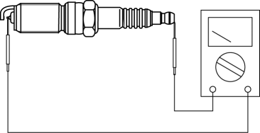
1. Measure the resistance of the spark plug using a tester as shown in the figure.

-
If not within specification, replace the spark plug.
-
Spark plug resistance [25°C {77 °F}]
-
3.0—7.5 kilohms
 Ignition System [Skyactiv G 2.0]
Outline
A direct ignition coil for independent ignition control has been adopted.
An ignition coil built-into the ion sensor has been adopted.
An iridium spark plug has been ado ...
 Spark Plug Removal/Installation [Skyactiv G 2.0]
CAUTION:
If a spark plug that is not as specified is installed, engine performance
will be deteriorated. Install only the specified spark plug when replacing.
1. Disconnect the negati ...
Other materials:
Cowl Upper Plate Installation [Panel Replacement]
Symbol Mark
Installation Procedure
1. When installing new parts, measure and adjust the body as necessary to conform
with standard dimensions.
2. Drill holes for the plug welding before installing the new parts.
3. After temporarily installing new parts, make sure the related parts fit p ...
Outside the United States/Canada
Government regulations in the United States/Canada require that automobiles meet
specific emission regulations and safety standards. Therefore, vehicles built for
use in the United States/Canada may differ from those sold in other countries.
The differences may make it difficult or even impossi ...
Seat Warmer Unit Inspection
WARNING:
Handling a side air bag improperly can accidentally operate (deploy) the
air bag, which may seriously injure you. Read the service warnings/cautions
in the Workshop Manual before handling the front seat (side air bag integrated)..
CAUTION:
If the slide bar is ope ...
