Mazda CX-5 Service & Repair Manual: Side Wall Removal/Installation
1. Pull the side wall in the direction of the arrow in the order of (1), (2) and remove it while detaching hooks A and clip B.
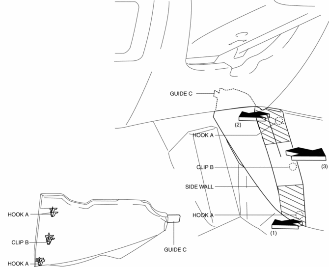
2. Pull the side wall in the direction of the arrow (3) and remove it while detaching the guide C.
CAUTION:
-
If the hooks A and clip B is removed forcefully, guide C may be damaged. Carefully remove hooks A and clip B so as not to damage guide C.
3. Install in the reverse order of removal.
 Shift Panel Removal/Installation
ATX
1. Disconnect the negative battery cable..
2. Selector lever to neutral position.
3. Remove the front console box..
4. Take the shaded area shown in the figure, and remove the shift panel i ...
 Switch Panel Removal/Installation
1. Disconnect the negative battery cable..
2. Remove the car-navigation unit. (with car-navigation system).
3. Insert your hand from the lower side of the lower panel (without car-navigation
sys ...
Other materials:
Drive Belt Removal/Installation
WARNING:
A hot engine can cause severe burns. Turn off the engine and wait until it
is cool before servicing.
NOTE:
Remove/install the drive belt from the underside of the vehicle.
Generator Drive Belt Removal/Installation
CAUTION:
To prevent damage to the dri ...
Windshield Wiper Motor Inspection
1. Disconnect the negative battery cable..
2. Remove the following parts:
a. Windshield wiper arm and blade.
b. Cowl grille.
Windshield Wiper Motor Inspection
1. Apply battery positive voltage and connect the ground to the windshield wiper
motor terminals as indicated in the table below a ...
Hill Launch Assist (Hla)
Purpose/Function
The hill launch assist (HLA) is a function which assists the driver in accelerating
the vehicle on a slope by activating the traction control solenoid valve in
the DSC HU/CM when the vehicle begins accelerating on a slope, and maintaining/reducing
brake fluid pressur ...
