
Mazda CX-5 Service & Repair Manual: Shroud Upper Reinforcement Installation [Panel Replacement]
Symbol Mark

Installation Procedure
1. When installing new parts, measure and adjust the body as necessary to conform with standard dimensions.
2. Drill holes for the plug welding before installing the new parts.
3. After temporarily installing new parts, make sure the related parts fit properly.
4. Plug weld the 4 locations shown in the figure, then install the shroud upper reinforcement.
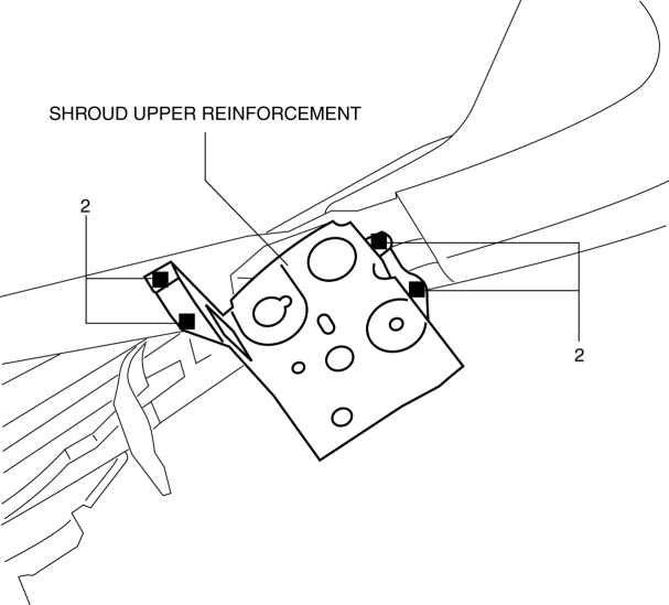
 Shroud Upper Member Removal/Installation
1. Disconnect the negative battery cable..
2. Remove the following parts:
a. Seal board upper.
b. Front bumper.
c. Front combination light.
3. Remove bolts.
4. Remove the shroud upper ...
 Shroud Upper Reinforcement Removal [Panel Replacement]
Symbol Mark
Removal Procedure
1. Drill the 4 locations shown in the figure.
NOTE:
When drilling the 4 locations shown in the figure, do not drill a hole all
the way through or there ...
Other materials:
Disc Pad (Front) Replacement
1. Remove in the order indicated in the table.
2. Install in the reverse order of removal.
3. After installation, depress the brake pedal a few times, rotate the wheel
by hand, and verify that the brake does not drag.
1
Bolt
2
Caliper
...
Fuel Filler Lid Opener Cable Removal/Installation
1. Disconnect the negative battery cable..
2. Remove the following parts:
a. Front scuff plate (LH).
b. Front seat (LH).
c. Rear scuff plate.
d. B-pillar lower trim (LH).
e. Rear seat (4:2:4 split type).
f. Rear seat cushion (6:4 split type).
g. Rear seat back (6:4 split type).
h. ...
Down Switch [Fw6 A EL, Fw6 Ax EL]
Purpose/Function
The down switch detects the shift down operation of the selector lever.
The down switch signal is sent to the TCM via CAN and is used for manual
shift control and engine-transaxle integration control.
Construction
The down switch is installed to the se ...
