Mazda CX-5 Service & Repair Manual: Refrigerant Pressure Sensor [Full Auto Air Conditioner]
Purpose
-
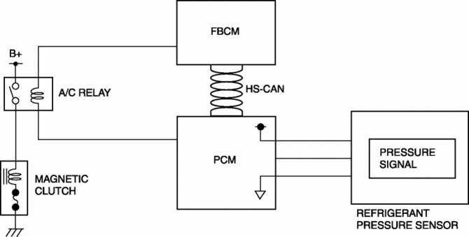
The refrigerant pressure sensor detects the refrigerant pressure in the refrigerant cycle.
Function
-
The refrigerant pressure sensor converts the detected refrigerant pressure to an electric signal and sends it to the PCM.
Construction
-
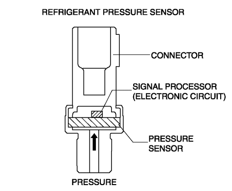
The refrigerant pressure sensor is installed on the cooler pipe.
-
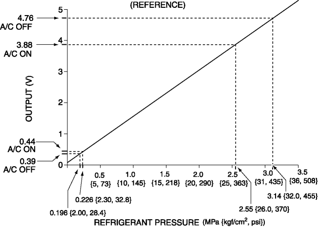
A capacitance type refrigerant pressure sensor, which converts refrigerant pressure into a linear electric signal, has been adopted.
-
Consists of a pressure detecting part and signal processing part.
-
The pressure detecting part is a variable capacity condenser, which changes capacitance according to the pressure.
-
The signal processing part detects the capacitance of pressure detecting part, converts it to voltage, then outputs it to the climate control unit.
Operation
Capacitance type
-
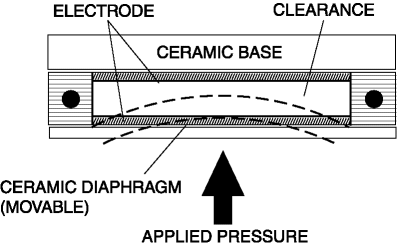
There is a clearance between the movable ceramic diaphragm and the ceramic base, and each side has an electrode.
-
When pressure is applied from the ceramic diaphragm side, the ceramic diaphragm deforms, and the clearance between the electrodes changes. As a result, capacitance is changed and pressure is detected.
Fail-safe
-
Function not equipped.
 Refrigerant Pressure Sensor Removal/Installation [Manual Air Conditioner]
1. Disconnect the negative battery cable..
2. Discharge the refrigerant..
3. Disconnect the refrigerant pressure sensor connector.
CAUTION:
If moisture or foreign material enters the ref ...
 Refrigerant Pressure Sensor [Manual Air Conditioner]
Purpose
The refrigerant pressure sensor detects the refrigerant pressure in the refrigerant
cycle.
Function
The refrigerant pressure sensor converts the detected refrigerant pre ...
Other materials:
TCM Configuration [Fw6 A EL, Fw6 Ax EL]
NOTE:
The TCM is built into the control valve body.
1. Verify TCM configuration implementation necessity for replacement parts.
Replacement part
Configuration necessity
Control valve body replacement
Necessary
...
Brake Fluid Level Sensor Inspection
1. Disconnect the brake fluid level sensor connector from the master cylinder.
2. Inspect for continuity according to fluid level between the brake fluid level
sensor terminals.
If not as indicated in the table, replace the reserve tank..
...
Steering Angle Sensor Inspection
1. Remove the column cover..
2. Connect the plus (+) end of a tester to steering angle sensor terminal A and
the minus (-) end of the tester to terminal B (GND).
3. Switch the ignition ON (engine off or on).
4. Turn the steering wheel to the left and right.
5. Verify that the voltage f ...
