Mazda CX-5 Service & Repair Manual: Rear Stabilizer Removal/Installation [Awd]
WARNING:
-
Verify that the rear crossmember is securely supported by a jack. If the rear crossmember falls off, it can cause serious injury or death, and damage to the vehicle.
CAUTION:
-
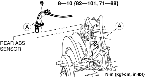
Performing the following procedures without first removing the rear ABS wheel-speed sensor may possibly cause an open circuit in the harness if it is pulled by mistake. Before performing the following procedures, disconnect the rear ABS wheel-speed sensor (axle side) and fix it to an appropriate place where the sensor will not be pulled by mistake while servicing the vehicle.
1. Disconnect the rear auto leveling sensor link. (With auto leveling sensor).
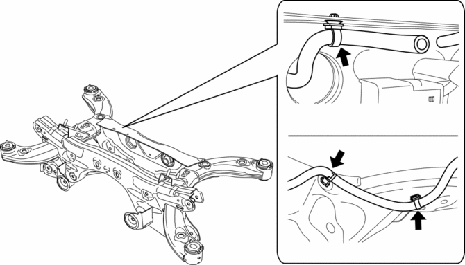
2. Disconnect the wiring harness clips and connectors installed to the rear crossmember.
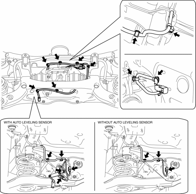
3. Set the rear differential breather hose aside.
4. Disconnect the rear ABS wheel-speed sensor wiring harness installed to the hub support and set it aside..
5. Remove the propeller shaft..
6. Remove the TWC..
7. Remove the rear coil spring..
8. Remove in the order indicated in the table.
9. Install in the reverse order of removal.
10. Inspect the wheel alignment and adjust it if necessary..
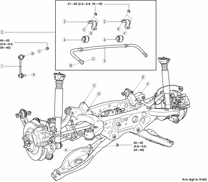
|
1 |
Rear stabilizer control link |
|
2 |
Rear stabilizer component (See Rear Stabilizer Component Removal Note.) (See Rear Stabilizer Component Installation Note.) |
|
3 |
Rear stabilizer bracket (See Rear Stabilizer Component Installation Note.) |
|
4 |
Rear stabilizer bushing (See Rear Stabilizer Component Installation Note.) |
|
5 |
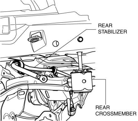
Rear stabilizer |
Rear Stabilizer Component Removal Note
1. Support the rear crossmember component with a jack and remove the rear crossmember installation nuts.
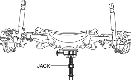
2. Press down on the rear crossmember component until the rear stabilizer component can be removed from the vehicle using a jack.
Rear Stabilizer Bracket Removal Note
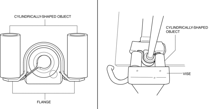
1. Secure the rear stabilizer bracket flange using a vise.
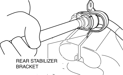
Rear Stabilizer Bushing, Rear Stabilizer Bracket Installation Note
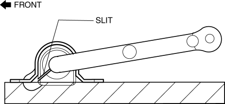
1. Install the rear stabilizer bushing with the slit pointing toward the front of the vehicle.
2. Install the rear stabilizer bracket to the front stabilizer bushing by hand using the following procedure.
3. If the rear stabilizer bracket cannot be installed by hand, install it using a vice.
CAUTION:
-
If the rear stabilizer bracket is installed using a vice, it could be deformed.
-
Set a cylindrically-shaped object as shown in the figure so that pressure is applied to the raer stabilizer bracket flange, and install the raer stabilizer bracket to the raer stabilizer bushing.
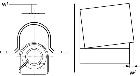
4. During rear stabilizer bracket installation, keep the deviation in the positions of the rear stabilizer bracket and the rear stabilizer bushing within the range shown in the figure.
-
W1: 0.5 mm {0.21 in} max.
-
W2: 2 mm {0.08 in} max.
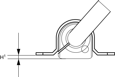
5. After installing the rear stabilizer bracket, verify that the positions of the rear stabilizer bracket and the rear stabilizer bushing are within the range shown in the figure.
-
H1: 13 mm {0.51 in} max.
6. After installing the rear stabilizer bracket, verify that the right and left-side positions of the rear stabilizer bracket are within the range shown in the figure.
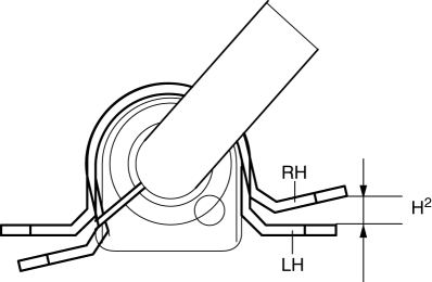
-
H2: 3 mm {0.1 in} max.
7. Place the rear stabilizer component on a level workbench, and verify that it is within the range shown in the figure.
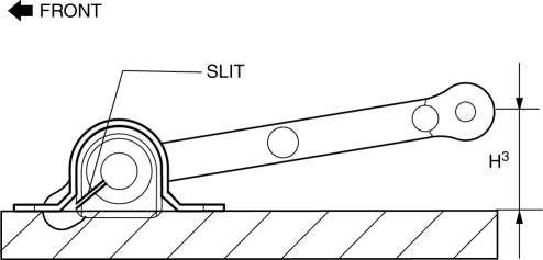
-
H3: 41.8—51.8 mm {1.65—2.03 in}
Rear Stabilizer Component Installation Note
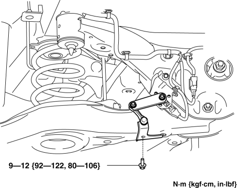
1. Temporarily tighten bolts A and B shown in the figure.
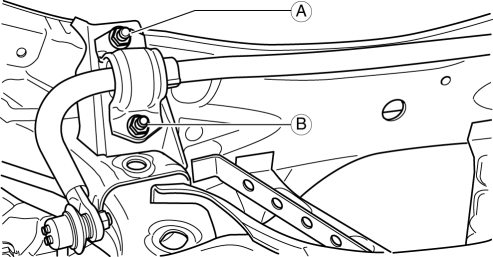
2. Tighten bolt A.
-
Tightening torque
-
21—26 N·m {9.3—11 kgf·m, 16—19 ft·lbf}
3. Tighten bolt B.
-
Tightening torque
-
21—26 N·m {9.3—11 kgf·m, 16—19 ft·lbf}
4. Tighten bolt A.
-
Tightening torque
-
21—26 N·m {9.3—11 kgf·m, 16—19 ft·lbf}
5. Lift up the rear crossmember component using a jack and install the rear crossmember installation nuts.
-
Tightening torque
-
91—111 N·m {9.3—11 kgf·m, 68—81 ft·lbf}
 Rear Crossmember Removal/Installation [Awd]
WARNING:
Verify that the crossmember is securely supported by a jack. If the rear
crossmember falls off, it can cause serious injury or death, and damage to the
vehicle.
CAUTION:
...
 Rear Upper Arm Removal/Installation [Awd]
WARNING:
Verify that the crossmember is securely supported by a jack. If the rear
crossmember falls off, it can cause serious injury or death, and damage to the
vehicle.
CAUTION:
...
Other materials:
Driving In Flooded Area
WARNING
Dry off brakes that have become wet by driving slowly, releasing the accelerator
pedal and lightly applying the brakes several times until the brake performance
returns to normal:
Driving with wet brakes is dangerous. Increased stopping distance or the vehicle
pulling to one side whe ...
Shift Solenoid No.2 [Fw6 A EL, Fw6 Ax EL]
Purpose/Function
Shift solenoid No.2 adjusts the hydraulic pressure in the 2-6 brake circuit
based on the current demand from the TCM according to the vehicle conditions.
Construction
Shift solenoid No.2 is installed to the solenoid control valve body.
Shift solenoid N ...
Rear Mount Camera
Purpose, Function
The rear mount camera shoots the conditions at the rear of the vehicle in
color, and after converting the video signal, it outputs the signal to the audio
unit. (with color LCD)
Construction
The rear mount camera is installed onto the liftgate.
...
