Mazda CX-5 Service & Repair Manual: Rear Mount Camera Removal/Installation
CAUTION:
-
The audio unit communicates with the rear mount camera and records the presence/non-presence of the rear mount camera when the ignition is switched to ACC or ON (engine off or on) after connecting the negative battery cable.
-
If the commander switch is installed with the negative battery cable connected when the audio unit records that there is no rear mount camera, the rear mount camera does not operate.
-
For the rear mount camera installation/removal, disconnect the negative battery cable, switch the ignition to ACC or ON (engine off or on) after the servicing is completed, and the audio unit records the presence/non-presence of the rear mount camera.
1. Disconnect the negative battery cable..
2. Remove the following parts:
a. Liftgate upper trim.
b. Liftgate side trim.
c. Liftgate recess.
d. Liftgate lower trim.
e. Liftgate garnish.
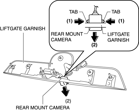
3. Press the back monitor camera tabs in the direction of the arrows (1) shown in the figure, pull the back monitor camera in the direction of the arrow (2) shown in the figure, and disengage the back monitor camera tabs from the liftgate garnish.
4. Remove the rear mount camera.
5. Install in the reverse order of removal.
 Rear Mount Camera Inspection
1. Disconnect the negative battery cable..
2. Remove the following parts:
a. Liftgate upper trim.
b. Liftgate side trim.
c. Liftgate lower trim.
d. Liftgate garnish.
e. Rear mount camera. ...
 Sirius Satellite Radio Unit
Purpose
Satellite radio programming can be listened to.
Function
The voltage signal sent from the center roof antenna (SIRIUS satellite radio
antenna) is output to the audio uni ...
Other materials:
Parking Brake Lever Inspection
Stroke Inspection
1. Pump the brake pedal a few times.
2. Pull the parking brake lever two to three times.
3. Inspect the parking brake stroke by slowly pulling at point A 50 mm {2.0
in} from the end of the parking brake lever with a force of 98 N {10 kgf,
22 lbf} and counting the number of ...
Brake Fluid Pressure Sensor Inspection
1. Switch the ignition to off.
2. Remove the clips.
3. Set the splash shield out of the way.
4. Disconnect the brake pipe from the LF brake hose.
5. Remove the clip.
6. Remove the LF brake hose from the bracket.
7. Detach the brake pipe from the pipe holder.
8. Install the SST ...
Instrument Cluster Inspection
Speedometer inspection
Using a speedometer tester
1. Adjust the tire pressure to the specification.
2. Using a speedometer tester, verify that the tester reading is as indicated
in the following table. km/h
Speedometer tester indication (km/h)
Allowable rang ...
