Mazda CX-5 Service & Repair Manual: Purge Control
Outline
-
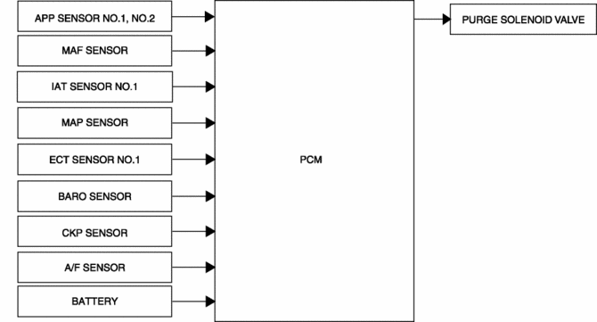
An appropriate amount of evaporative gas is fed into the intake manifold by the purge solenoid valve operation according to the engine operation conditions. This ensures driveability and prevents release of evaporative gas into the atmosphere.
-
The PCM drives the purge solenoid valve based on the signal from each control part.
Block Diagram
Operation
Determination of purge solenoid valve energization time
-
The PCM determines energization time based on purge flow amount. In addition, it corrects the energization time according to fluctuations in battery positive voltage (the lower the rate of battery positive voltage, the longer the energization time).
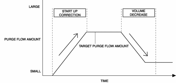
Calculation method for purge flow amount
-
The PCM determines the purge flow amount through the addition of each correction to the target purge flow amount.
|
Contents |
Calculation or determination method of purge flow amount and correction |
|
|
Target purge flow amount |
The target purge flow amount is determined by multiplying the correction for the intake air temperature and the fuel evaporative gas concentration with the purge mass volume. The purge mass volume is calculated from the purge intake rate for the intake air mass volume which differs according to engine conditions. |
|
|
Correction |
Startup correction |
Purpose: Prevents a change in the air/fuel ratio due to a purge intake lacking evaporative gas concentration in the charcoal canister.
|
|
Volume decrease correction |
Purpose: Decreases the purge flow amount and stabilizes the air/fuel ratio.
|
|
Purge control image
Operation condition
-
In evaporative purge control during normal driving, the PCM sends a duty signal to the purge solenoid valve when all of the following conditions are met.
-
Fuel injection control is in feedback zone (?=1)
-
Engine coolant temperature 60 °C {140 °F} or more
 Pressure Sensor [Two Step Deployment Control System]
Purpose
The pressure sensor determines at an earlier stage whether to detonate the
air bag on the side of the vehicle (around front door) receiving an impact.
This is for improved accurac ...
 Room Light Control System
Outline
The room light control system changes the illumination condition and illumination
level of the interior lights (door position) according to whether the doors
are opened/closed and ...
Other materials:
Front ABS Wheel Speed Sensor Removal/Installation
1. Remove the mudguard..
2. Remove in the order indicated in the table.
3. Install in the reverse order of removal.
4. After installation, verify that there is no twisting in the front ABS wheel-speed
sensor.
1
Connector
2
Bolt
...
Slide Motor Inspection
WARNING:
Handling a side air bag improperly can accidentally operate (deploy) the
air bag, which may seriously injure you. Read the service warnings/cautions
in the Workshop Manual before handling the front seat (side air bag integrated)..
CAUTION:
When performing the pro ...
Drive Belt Inspection
Generator Drive Belt
NOTE:
The generator drive belt deflection/tension inspection is not necessary with
the adoption of the drive belt auto tensioner.
1. Verify that the indicator part of the cast hexagon on the drive belt auto
tensioner is within the normal range.
If ...
