Mazda CX-5 Service & Repair Manual: Power Window Motor
Purpose
The power window motor transmits rotation force to the power window regulator to open/close the door glass.
Function
The power window motor rotates clockwise/counterclockwise when it receives an open/close signal from the power window main switch or the power window subswitch.
Construction
-
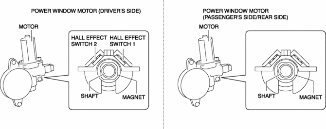
The power window motor consists of the following parts:
-
Motor
-
Connector
-
Gear
-
Two Hall effect switches are located in the driver's side connector.
-
The Hall effect switches output pulse to the P/W CM.
Operation
-
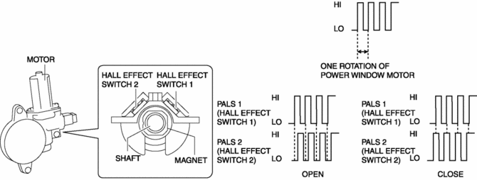
The Hall effect switch utilizes magnets set on a rotating axis to detect the motor rotation, and outputs a synchronized pulse to the P/W CM.
-
The Hall effect switch 1 outputs one pulse cycle for each rotation of the power window motor axle, and the P/W CM detects motor rotation speed.
-
Hall effect switch 2 outputs pulse according to the motor rotation in the same manner as Hall effect switch 1. The high and low pulse points of Hall effect switches 1 and 2 are different during opening and closing because the phase difference shifts by 90°, allowing the power window main switch to detect the rotational direction of the power window motor.
Fail-safe
-
Function not equipped
 Power Window Main Switch Removal/Installation
1. Disconnect the negative battery cable..
2. Remove the cover A.
3. Insert a tape-wrapped fastener remover shown in the figure and remove the
tab B in the direction of arrow (1).
4. S ...
 Power Window Motor Inspection
Front driver side
1. Disconnect the negative battery cable..
2. Remove the inner garnish..
3. Remove the front door trim..
4. Disconnect the power window motor connector.
5. Apply battery pos ...
Other materials:
Anticorrosion, Sound Insulation, And Vibration Insulation
Body Sealing
Apply body sealer where necessary.
For locations where application of body sealer is difficult after installation,
apply it before installation.
Application of Undercoating
Apply an undercoat to the required location of the body.
Application ...
Floor Side Panel Installation [Panel Replacement]
Symbol Mark
Installation Procedure
1. When installing new parts, measure and adjust the body as necessary to conform
with standard dimensions.
2. Drill holes for the plug welding before installing the new parts.
3. After temporarily installing new parts, make sure the related parts fit p ...
Up Switch Inspection [Fw6 A EL, Fw6 Ax EL]
Continuity Inspection
NOTE:
The up switch is built into the selector lever component.
1. Disconnect the negative battery cable..
2. Remove the front console..
3. Disconnect the selector lever component connector.
4. Verify that the continuity between selector lever component ...
