Mazda CX-5 Service & Repair Manual: Power Supply Switching
Outline
-
By pressing the push button start, switching of the power supply is performed.
Function
-
The start stop unit switches the power supply according to the vehicle conditions such as the selector lever (ATX)/shift lever (MTX) position and the pedal depression/release when the push button start is pressed.
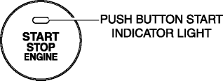
Push button start indicator light
-
Illuminates the push button start indicator light to notify the driver of the power supply status.
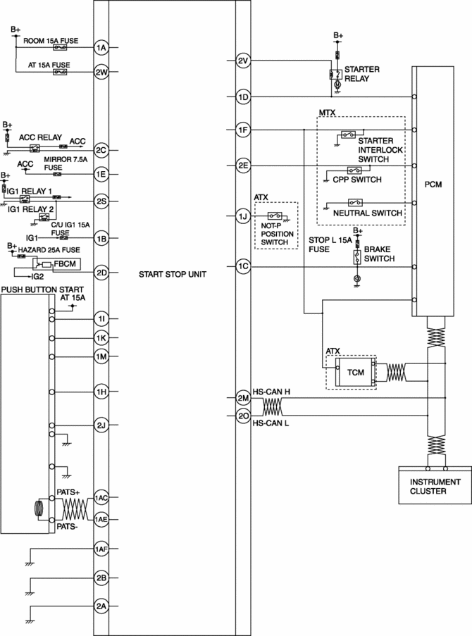
System wiring diagram

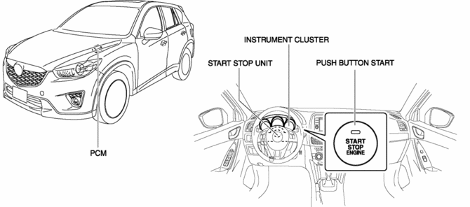
Structural view

Operation
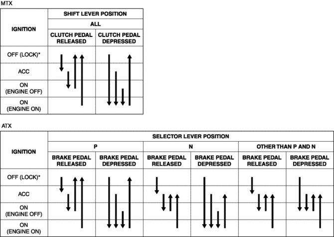
Switches between ignition switch ON (engine on)/ON (engine off)/ACC/ OFF (LOCK).
1. When the push button start is pressed, a push button start switch signal is input to the start stop unit.
2. The power supply switches according to the vehicle conditions such as the selector lever (ATX)/shift lever (MTX) position and the pedal depression/release.
NOTE:
-
Refer to the Push Button Start System Engine Start Permit Function regarding the engine starting conditions.

* To switch the ignition to ACC or off (LOCK) from ON (engine on), a vehicle speed of 5 km/h {3 mph} or less is required.
Automatic ignition switch off
-
If the ignition has been switched ON (engine off) or switched to ACC for 60 min or more, the start stop unit automatically switches the ignition off (LOCK).
Engine Emergency Stop
-
If an ignition switch ON signal is input for 3 s or more (ignition switch held pressed), or a push button start ON signal is input 3 times within 1.5 s, the start stop unit switches the ignition to ACC or off (LOCK).
Push button start indicator light
-
Green illumination
-
Illuminates if the conditions necessary for engine-start are met.
-
Green flashing
-
Flashes when the steering lock cannot be released.
-
Amber illumination
-
Illuminates when the steering lock has been released or there is a malfunction in the system.
-
Amber flashing
-
Flashes when a malfunction is detected.

Fail-safe
-
Function not equipped.
 Ignition
...
Other materials:
Starting the Engine
WARNING
Radio waves from the key may affect medical devices such as pacemakers: Before
using the key near people who use medical devices, ask the medical device manufacturer
or your physician if radio waves from the key will affect the device.
NOTE
• The key must be carried because the
ke ...
Washer Fluid Level Sensor Inspection
1. Disconnect the negative battery cable..
2. Set the front over fender aside..
3. Set the mudguard (RH) aside..
4. Remove the front bumper..
5. Inspect for continuity according to washer fluid level between the washer
fluid-level sensor terminals.
If not as indicated in th ...
Connecting Rod, Connecting Rod Bearing
Purpose, Function
Connecting rod
The connecting rod transmits the reciprocating movement of the piston to
the crankshaft by engaging the piston pin and crank pin.
Connecting rod bearing
The connecting rod bearing forms an oil film on the outer surface of the
crank pin to p ...

